
Hand tool machine having an oscillatory drive

a hand tool machine and oscillator technology, applied in the field of hand tool machines, can solve the problems of large production complexity, rotational oscillation of the tool spindle, and disadvantages of hand tools of the type, and achieve the effect of simple and reliable structur

Active Publication Date: 2013-03-19
C & E FEIN GMBH & CO KG
View PDF24 Cites 644 Cited by
  • Summary
  • Abstract
  • Description
  • Claims
  • Application Information

AI Technical Summary

Benefits of technology

The technical effect of this patent is to provide an improved oscillatory drive that is easy to use and trustworthy.

Problems solved by technology

The oscillating lever is connected to a tool spindle in a rotationally fixed manner, such that a motion of the oscillating lever caused by the rotating eccentric portion results in a rotational oscillation of the tool spindle.
A rotational oscillation of a tool spindle can, in principle, be effected in an alternative manner by means of such a hand tool, but only with a large number of parts and with a large amount of structural space being required, determined by the position of the elements in relation to one another, which is disadvantageous for hand tools of the type stated at the outset.
Moreover, the greatest precision is to be required primarily at those portions intended to provide for the axial displaceability of the wobble bearing on its drive shaft with simultaneous rotational driving of the wobble bearing by the drive shaft, as a result of which the production complexity is greatly increased.

Method used


Image

  • Hand tool machine having an oscillatory drive
  • Hand tool machine having an oscillatory drive
  • Hand tool machine having an oscillatory drive

Examples


Embodiment Construction

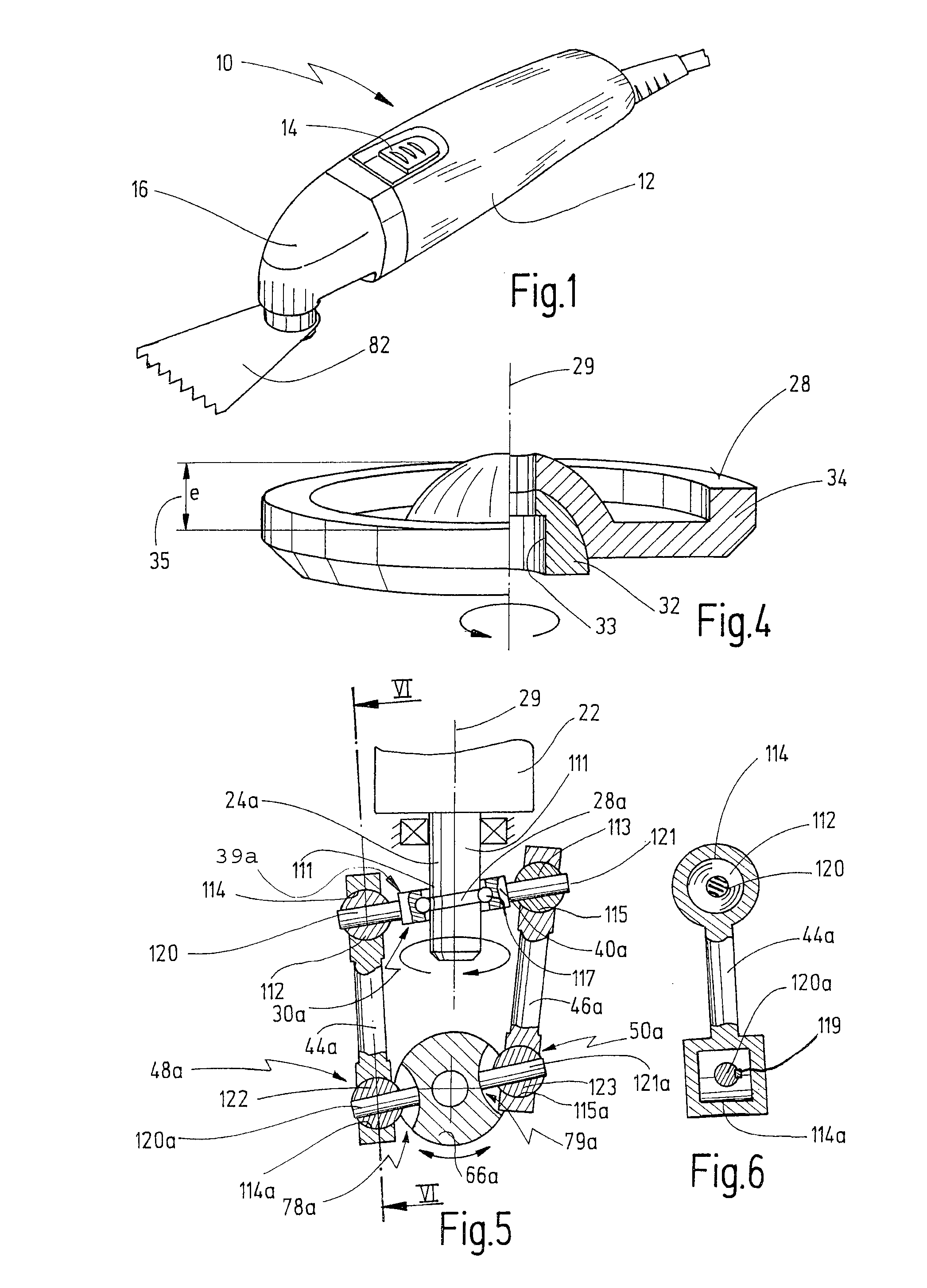
[0063]FIG. 1 shows a hand tool according to the invention, denoted in its entirety by 10. Indicated in this case is a housing 12, a switch 14 for activating the hand tool 10, a gearhead 16, and a tool 82 that can be driven in a rotationally oscillating manner by the hand tool 10.

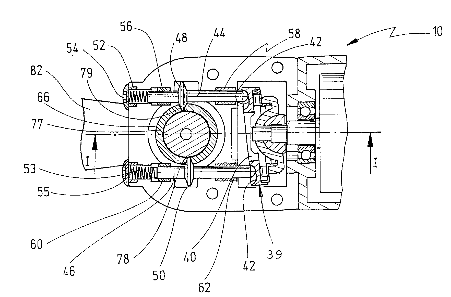
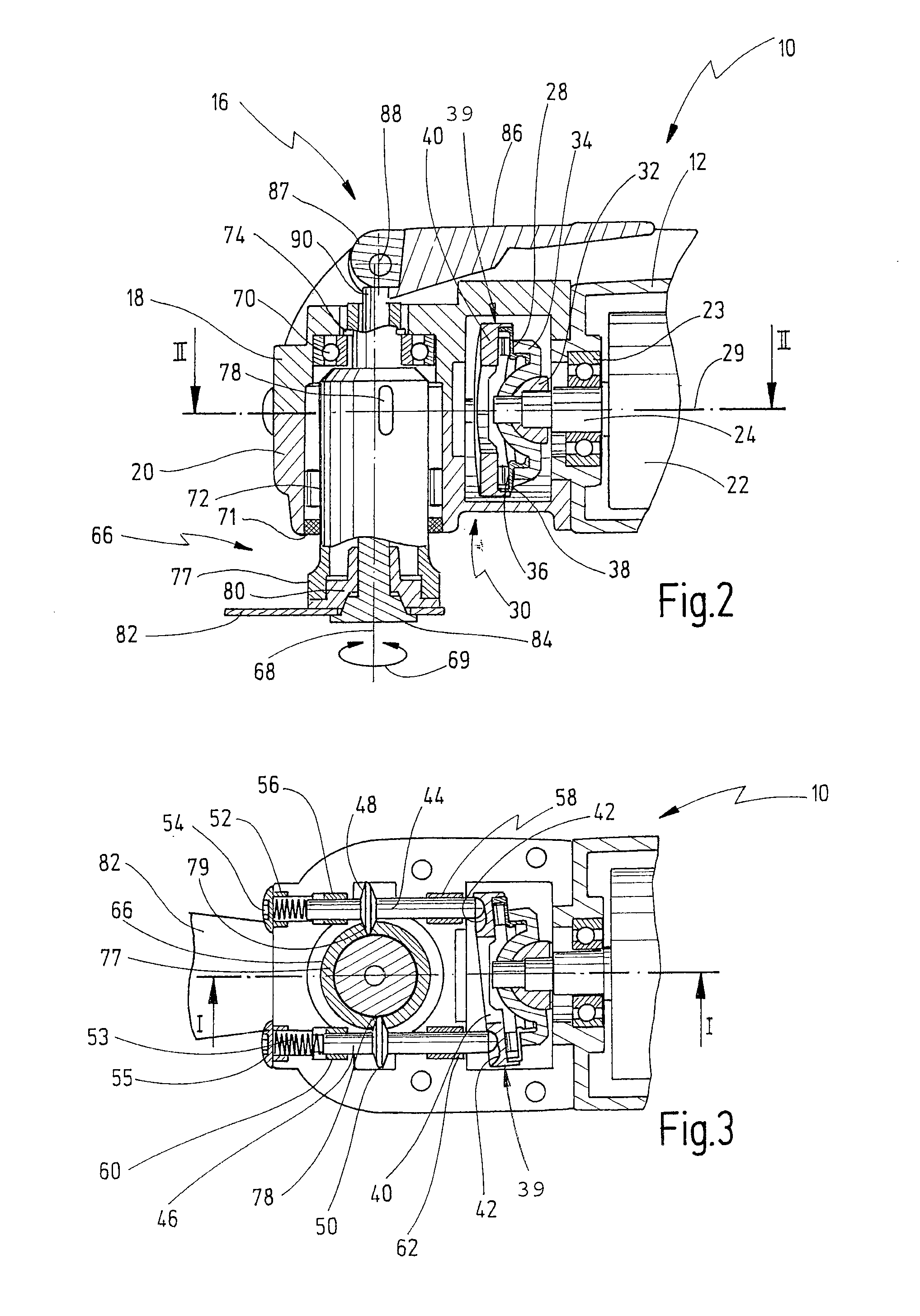
[0064]Represented in FIGS. 2 and 3 is such a hand tool 10 according to the invention, approximately according to the representation in FIG. 1, in section in the region of its gearhead, the structure of which is to be explained more fully in the following.

[0065]Arranged in the housing 12 is a drive motor 22 having a motor shaft 24 guided in a motor bearing 23. Flange-mounted on the tool-side end of the motor shaft 24 there is a wobble bearing, denoted as a whole by 30. In this case, a flange part 32 and a cup 34 are connected in a rotationally fixed manner, as a coupling element, to the motor shaft. This connection can be effected in a manner known in principle, for instance through pressing-on, by means of a...


PUM

PropertyMeasurementUnit
swivel anglesaaaaaaaaaa
swivel angleaaaaaaaaaa

Abstract

A hand tool is disclosed, comprising a housing, a motor shaft being coupled to a drive motor, a working spindle configured for being driven rotatingly oscillatingly about its longitudinal axis, and a coupling element being driven rotatingly by the motor shaft and having a closed guide surface that revolves around the motor shaft. The guide surface is coupled, via transmission means, to at least one driver for driving the latter. The at least one driver is arranged movably relative to the working spindle and engages the working spindle at a circumferential region thereof for driving the latter rotatingly oscillatingly.

Description

CROSS REFERENCES TO RELATED APPLICATIONS[0001]This application claims priority from German utility model application 202009011312.4, filed on Aug. 11, 2009. The entire contents of this priority application is incorporated herein by reference.BACKGROUND OF THE INVENTION[0002]The invention relates to a hand tool machine, having a housing, a motor shaft that is coupled to a drive motor, a working spindle that can be driven in a rotationally oscillating manner about its longitudinal axis, and a coupling element that can be driven rotationally by the motor shaft and has a closed guide surface that revolves about a guide axis, the guide surface being coupled, via transmission means, to at least one driver for the purpose of driving the latter.[0003]Such hand tools are known in principle in the prior art, for example from DE 80 31 084 U1. In the hand tool known from this application, the rotation of a motor shaft generated by a motor is transmitted to an oscillating lever by means of an ec...

Claims


Application Information

Patent Timeline
Patent Type & Authority Patents(United States)
IPC IPC(8): B23B45/16B25D9/00B25D11/00B25D13/00B25D16/00
CPCB24B23/028B27B19/006B25F5/00B24B23/04
Inventor BLICKLE, JUERGENKLABUNDE, OLAFWEBER, HEINRICH
Owner C & E FEIN GMBH & CO KG
Learn More