Outlet switch device and an outlet switch method

Active Publication Date: 2012-12-13
XIAMEN SOLEX HIGH TECH IND CO LTD
View PDF7 Cites 13 Cited by
  • Summary
  • Abstract
  • Description
  • Claims
  • Application Information

AI Technical Summary

Benefits of technology

[0032]7. the motion up and down of the switch plate drives the switch plate rotating, so the rotatio

Problems solved by technology

As the switch is realized by the user exerting rotation force to drive the water diversion body rotating relative to the fixed unit, there are disadvantages b

Method used


Image

  • Outlet switch device and an outlet switch method
  • Outlet switch device and an outlet switch method
  • Outlet switch device and an outlet switch method

Examples


Embodiment Construction

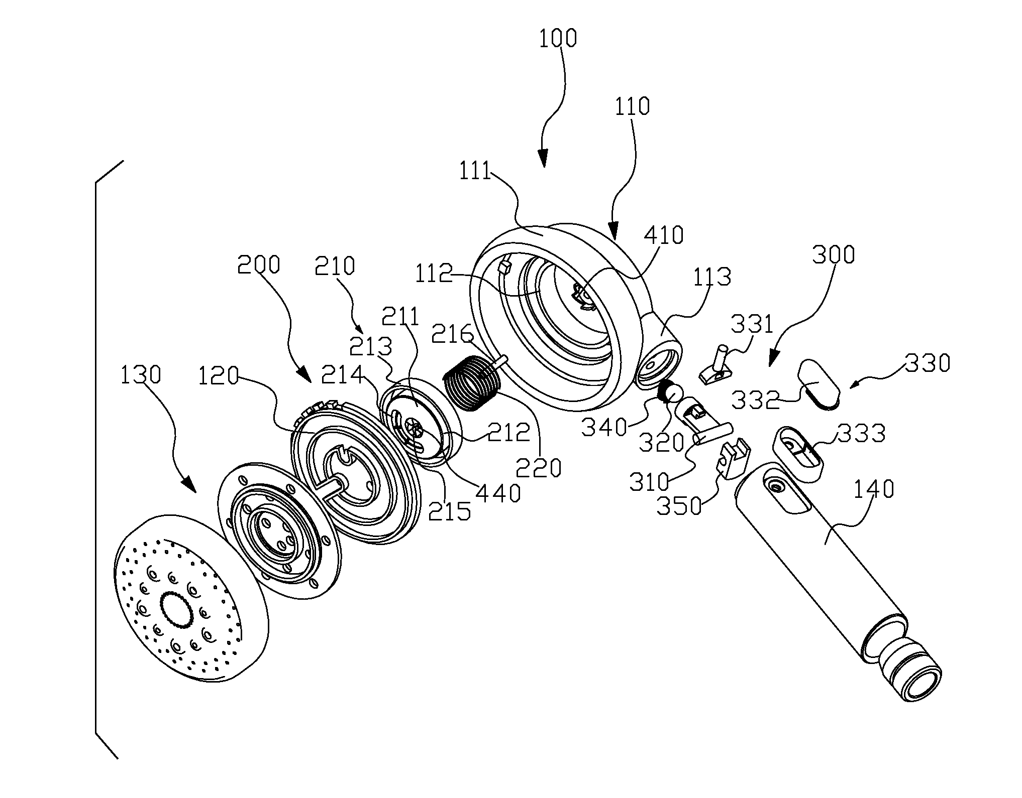
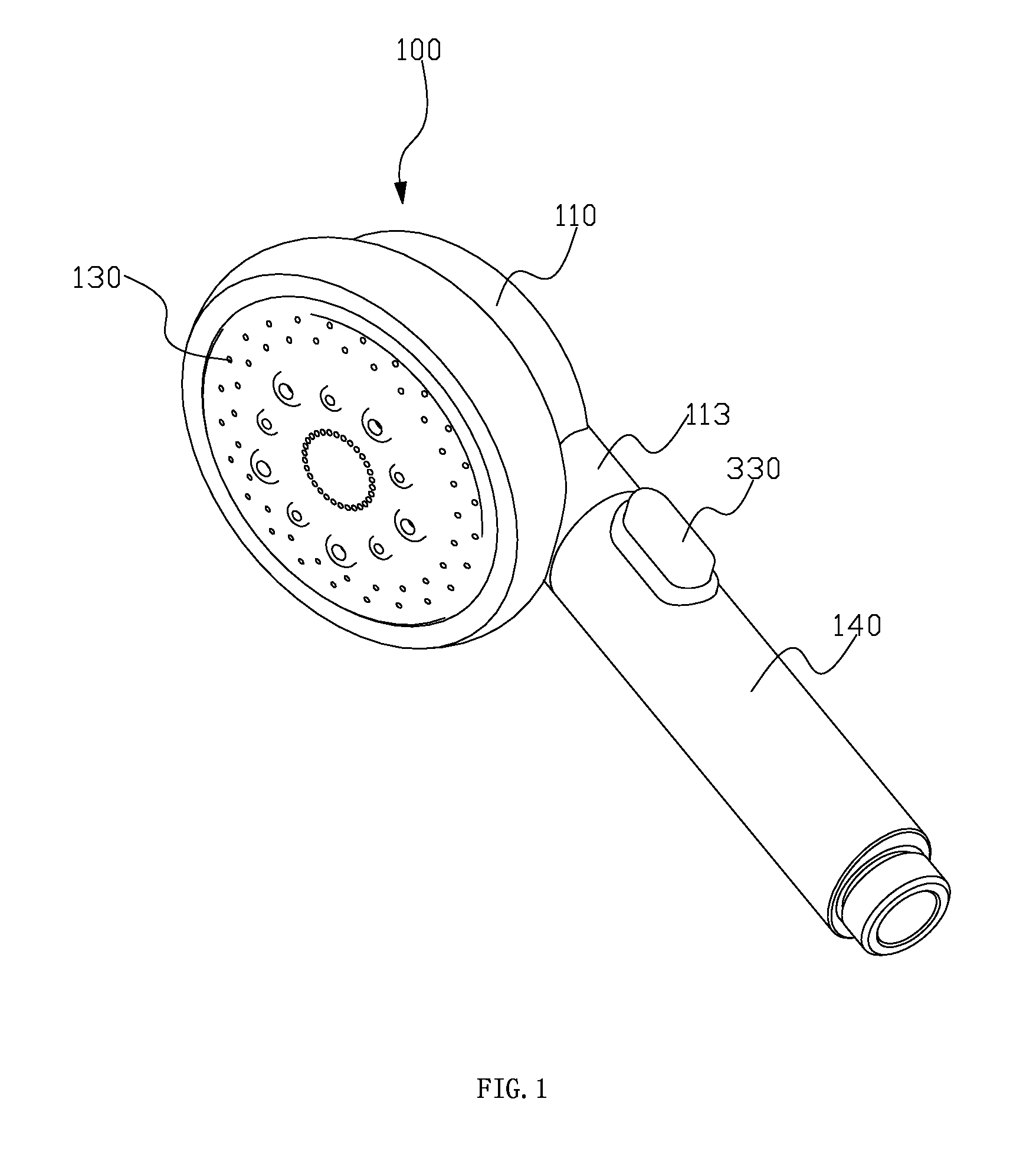
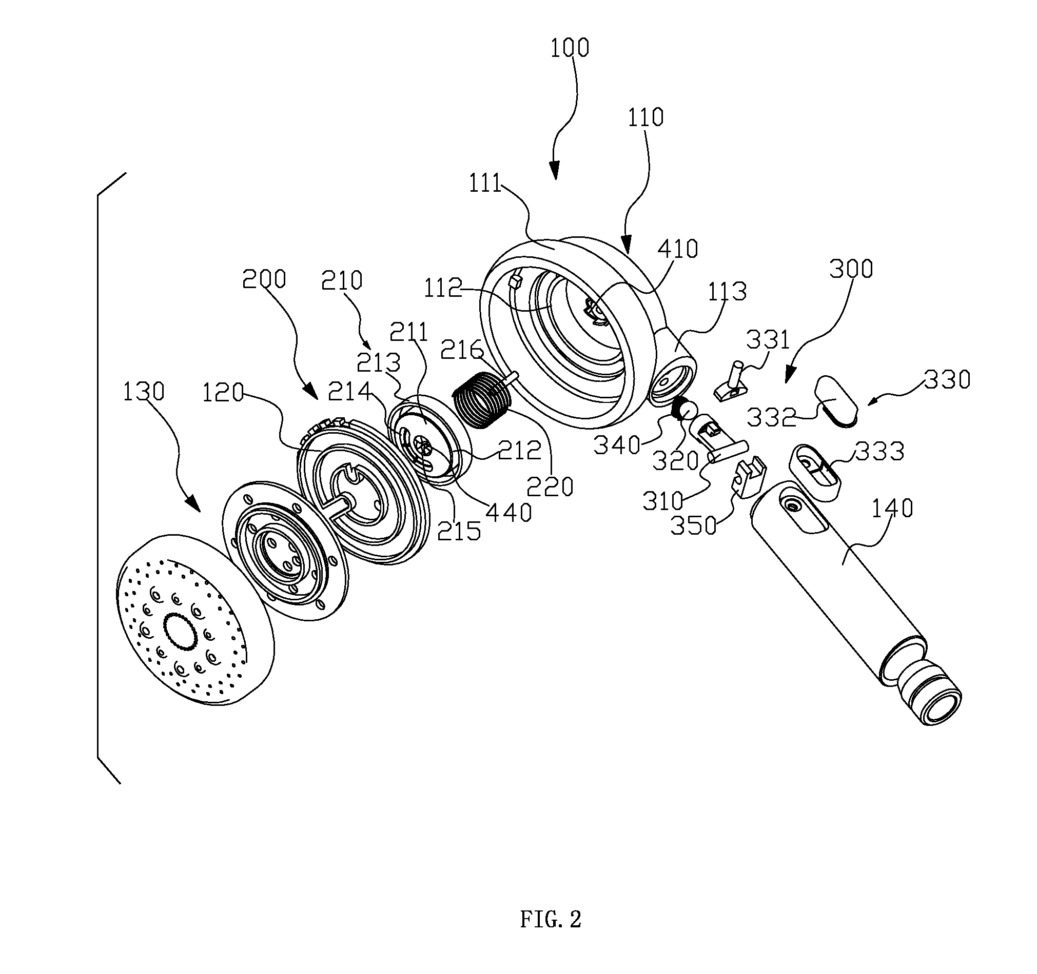
[0045]Refer to the FIG. 1, FIG. 2 and FIG. 3, the outlet switch device includes a fixed unit 100, an outlet switch mechanism 200, an inlet switch mechanism 300 and a driving device. In this embodiment, the outlet switch device is a shower, but not limited to this.

[0046]The fixed unit 100 includes a body 110, a water diversion plate 120, an outlet mechanism 130 and a handle 140. The body 110 includes a top board, a trumpet shaped sleeve 111 extended from the periphery of the top board, an upper inner periphery wall 112 fixed below the top board and situated inside the trumpet shaped sleeve coaxially and a joint 113 fixed outside the trumpet shaped sleeve. The handle 140 is screwed to the joint 113 to connect to the water, and an inlet cavity is disposed between the handle 140 and the joint 113. Two diversion waterways 114, 115 are disposed inside the body 110. The diversion waterways 114, 115 are separately defined as the upper diversion waterway 114 and lower diversion waterway 115,...


PUM


Abstract

The outlet switch device includes a fixed unit, an outlet switch mechanism, an inlet switch mechanism and a driving mechanism. The outlet function switch is realized through the relative rotation between the outlet switch mechanism and the fixed unit; the fixed unit includes a control cavity and an inlet waterway connected to the external water resource; the outlet switch mechanism includes a switch plate, which is movable connected inside the control cavity and divides the control cavity into an upper cavity and a lower cavity; the inlet switch mechanism controls the inlet waterway to control the water turning into the upper cavity or the lower cavity, making the switch plate move up and down with the effect of the water; the driving mechanism is disposed between the switch plate and the fixed unit to transform the action up and down to rotation.

Description


Claims


Application Information

Patent Timeline
Owner XIAMEN SOLEX HIGH TECH IND CO LTD
Why Eureka
Try Eureka