Driving apparatus and light amount adjustment apparatus

a technology of light amount adjustment and driving apparatus, which is applied in the direction of magnetic bodies, magnetic circuit shapes/forms/constructions, instruments, etc., can solve the problems of poor balance and significant loss, decreased output, and magnetic saturation, and achieves cost reduction, reduced output, and reduced equipment.

Inactive Publication Date: 2006-01-12
CANON KK
View PDF1 Cites 11 Cited by
  • Summary
  • Abstract
  • Description
  • Claims
  • Application Information

AI Technical Summary

Benefits of technology

[0012] The present invention has been proposed in view of the above-described problems, and has as its object to provide a driving app

Problems solved by technology

However, in the construction disclosed in the Japanese Patent Application Laid-Open No. 2002-049076, since there is only one tooth-shaped outer magnetic pole portion 103a, the magnet 101 upon rotation is pulled toward a direction opposite to the outer magnetic pole portion 103a, causing poor balance and a significant loss.
Since reducing the length of the magnet causes a decreased output, it is limited.
Since reducing the thickness of the outer magnetic pole portion 103a causes

Method used


Image

  • Driving apparatus and light amount adjustment apparatus
  • Driving apparatus and light amount adjustment apparatus
  • Driving apparatus and light amount adjustment apparatus

Examples


first embodiment

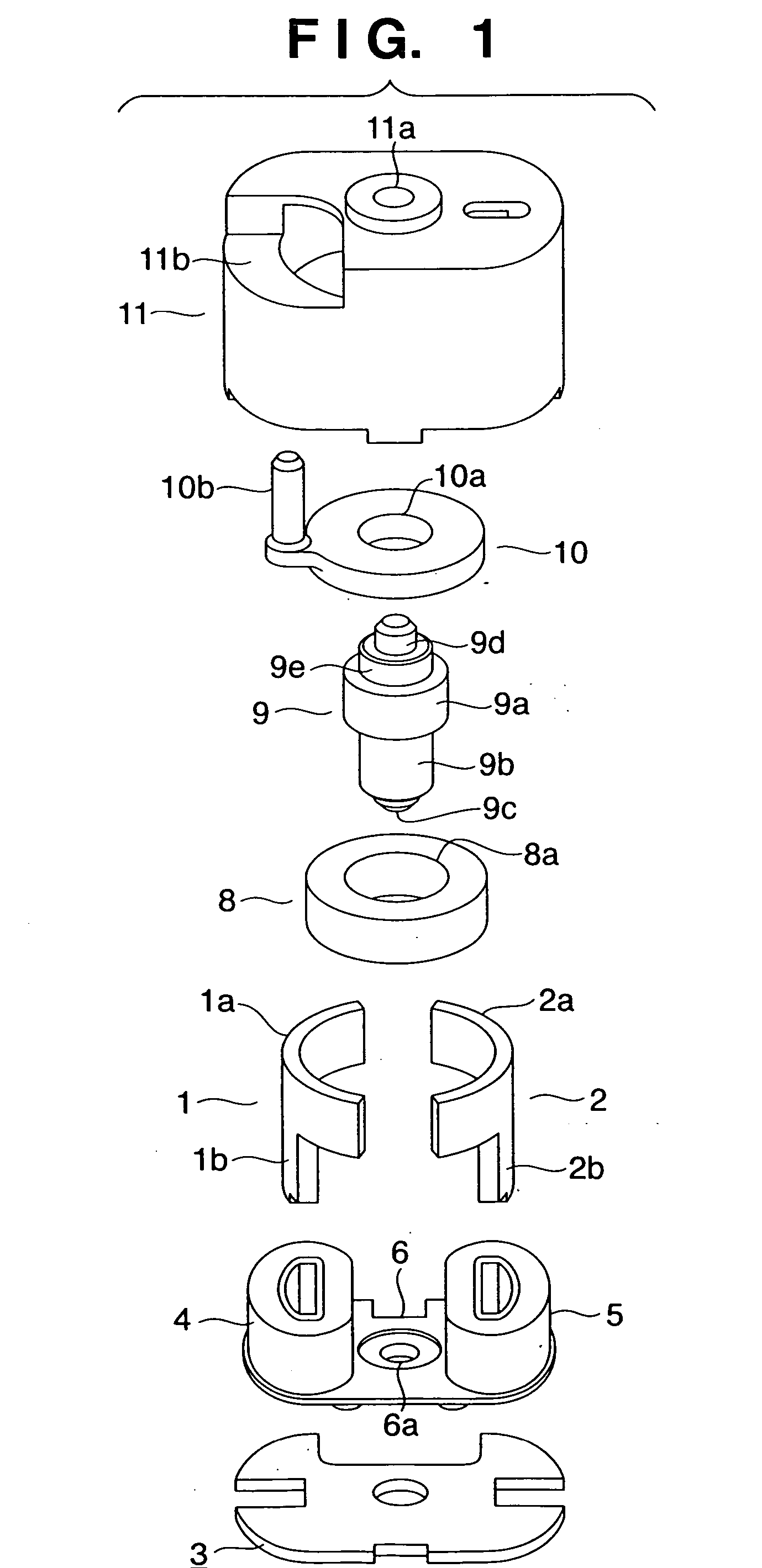
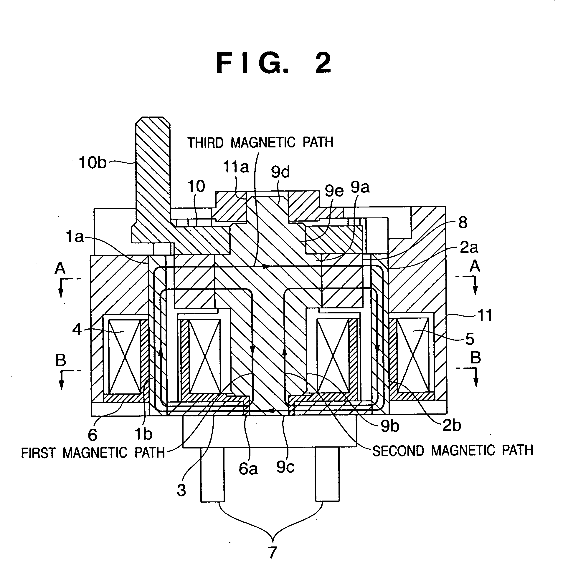
[0043] FIGS. 1 to 4 show a driving apparatus according to the first embodiment of the present invention. FIG. 1 is a breakdown perspective view; FIG. 2, a cross-section cut along the plane that is parallel to the central axis and that passes through the coil and the rotor axis; FIG. 3, a cross-section cut along the line A-A shown in FIG. 2; and FIG. 4, a cross-section cut along the line B-B shown in FIG. 2.

[0044] Referring to FIGS. 1 to 4, numeral 1 denotes a first outer magnetic pole portion formed with a soft magnetic material, consisting of a first magnet facing portion 1a and a first coil insertion portion 1b. Numeral 2 denotes a second outer magnetic pole portion formed with a soft magnetic material, consisting of a second magnet facing portion 2a and a second coil insertion portion 2b. Numeral 3 denotes a main yoke formed with a soft magnetic material, to which the first and second outer magnetic pole portions 1 and 2 are fixed by laser welding, bonding, press-fitting, or cau...

second embodiment

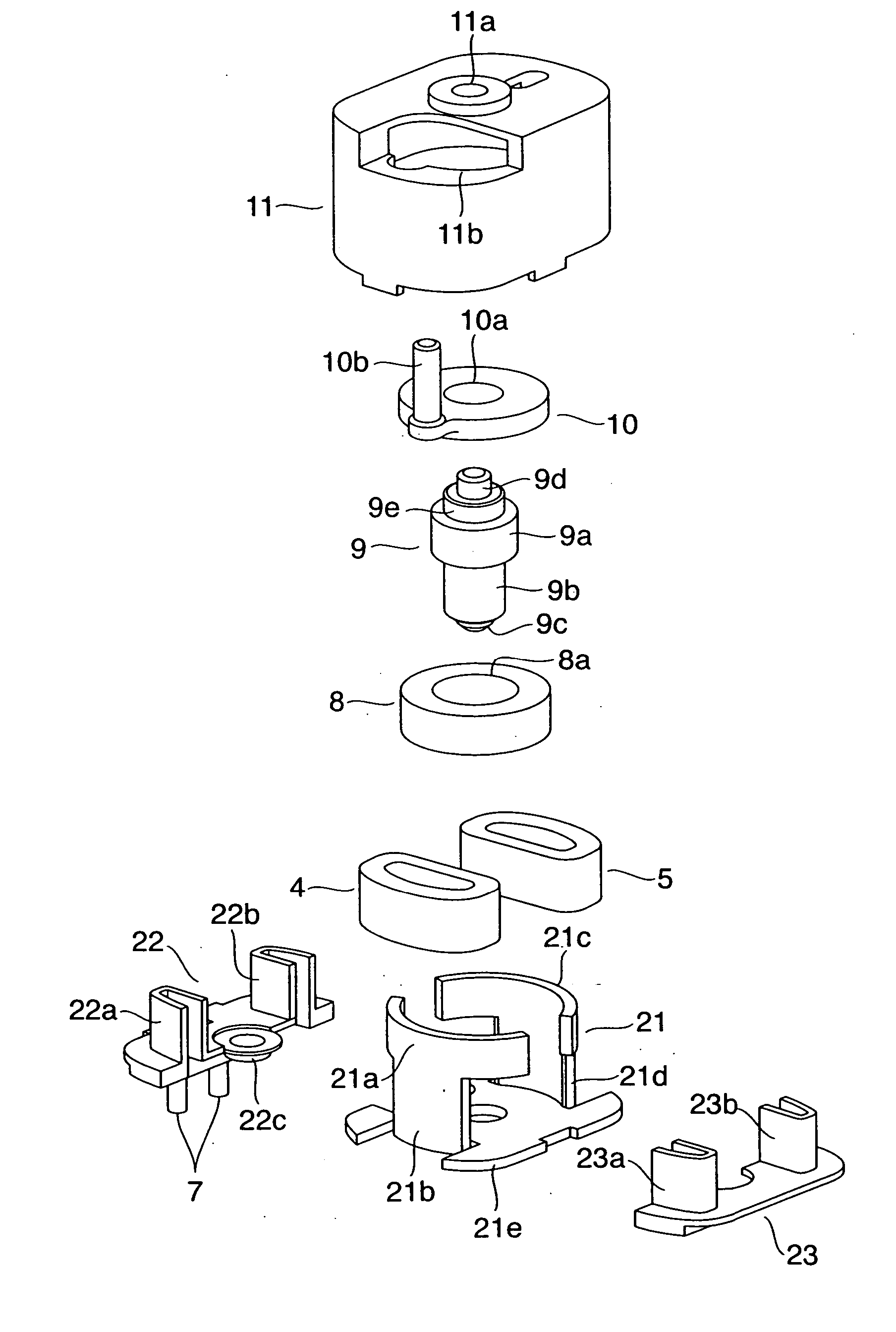
[0089]FIGS. 10 and 11 show a driving apparatus according to the second embodiment of the present invention. FIG. 10 is a breakdown perspective view of the driving apparatus, and FIG. 11 shows an assembled state of the driving apparatus, excluding a cover. In the following description, to the same components as those of the first embodiment, the same numerals are assigned and description thereof is omitted.

[0090] In the drawing, numeral 21 denotes a yoke formed with a soft magnetic material. The yoke 21 comprises a first magnet facing portion 21a, a first coil insertion portion 21b, a second magnet facing portion 21c, a second coil insertion portion 21d, and a connection portion 21e connecting the first coil insertion portion 21b with the second coil insertion portion 21d. These are integratedly formed by pressure molding.

[0091] Numeral 22 denotes a first bobbin; 23, a second bobbin. The first bobbin 22 comprises a first coil holder 22a, a second coil holder 22b, and a bearing 22c....


PUM


Abstract

The invention provides a driving apparatus comprising: a magnet that is magnetized to at least two poles in a circumferential direction and fixed to a rotor axis formed with a soft magnetic material; first and second coils arranged in the same direction as the magnet with respect to the magnet-axis direction and arranged adjacent to an end surface of the magnet in the magnet-axis direction; the first magnetic pole portion excited by energizing the first coil; the second magnetic pole portion excited to a pole opposite to the first magnetic pole portion by energizing the second coil; and a yoke portion formed with a soft magnetic material for supporting the first and second magnetic pole portions. The first magnetic pole portion includes a first coil insertion portion that is inserted to an internal diameter portion of the first coil, and a first magnet facing portion that is arranged to face a magnetized outer circumferential portion of the magnet with a predetermined gap at a predetermined angle. The second magnetic pole portion includes a second coil insertion portion that is inserted to an internal diameter portion of the second coil, and a second magnet facing portion that is arranged to face a magnetized outer circumferential portion of the magnet with a predetermined gap at a predetermined angle.

Description

FIELD OF THE INVENTION [0001] The present invention relates to a driving apparatus suitable for downsizing, and a light amount adjustment apparatus comprising the driving apparatus. BACKGROUND OF THE INVENTION [0002] Japanese Patent Application Laid-Open No. 2002-049076 discloses a driving apparatus incorporated in a light amount adjustment apparatus, which achieves an increased output and a small diametrical size with the rotation axis in the center. A breakdown perspective view of the driving apparatus is shown in FIG. 12, and a lateral cross-section is shown in FIG. 13. [0003] Numeral 101 denotes a magnet comprising a permanent magnet, which is capable of rotating on a rotation center, and whose outer circumferential surface is divided into two in the circumferential direction so as to be magnetized to the south pole and the north pole alternately. Numeral 102 denotes a coil arranged in the axial direction of the magnet 101. Numeral 103 denotes a stator, which is excited by the c...

Claims


Application Information

Patent Timeline
IPC IPC(8): H02K1/12H01F7/08
CPCH02K26/00
Inventor MIZUMAKI, MASAO
Owner CANON KK
Why Eureka
Try Eureka