Hinge construction

a construction and worm gear technology, applied in the direction of mountings, optics, instruments, etc., can solve the problems of not allowing easy mounting of worm gears and motor drive noise levels as low as possibl

Active Publication Date: 2011-03-24
SMR PATENTS S A R L
View PDF2 Cites 14 Cited by
  • Summary
  • Abstract
  • Description
  • Claims
  • Application Information

AI Technical Summary

Benefits of technology

[0014]By coupling the drive mechanism disengageably with one of the hinge parts, what can be achieved is that...

Problems solved by technology

In addition the noise level of the motor drive must be as low as possible fo...

Method used


Image

  • Hinge construction
  • Hinge construction
  • Hinge construction

Examples


Embodiment Construction

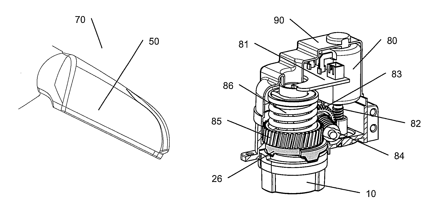
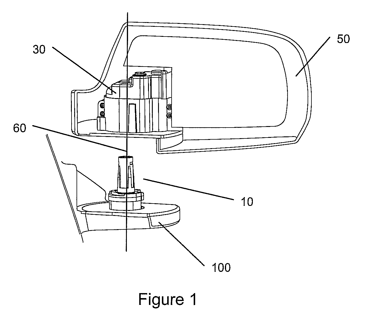
[0035]In FIG. 1 a wing minor with a base 100 and a minor head 50 is shown. A shaft 10 is fixed on the base 100 and the rest of power fold module 30 is mounted on the minor head 50.

[0036]This mechanism is working in that the power fold module 30 including the mirror head 50 rotates around the shaft 10 to the specific position (fold-in position and operational position).

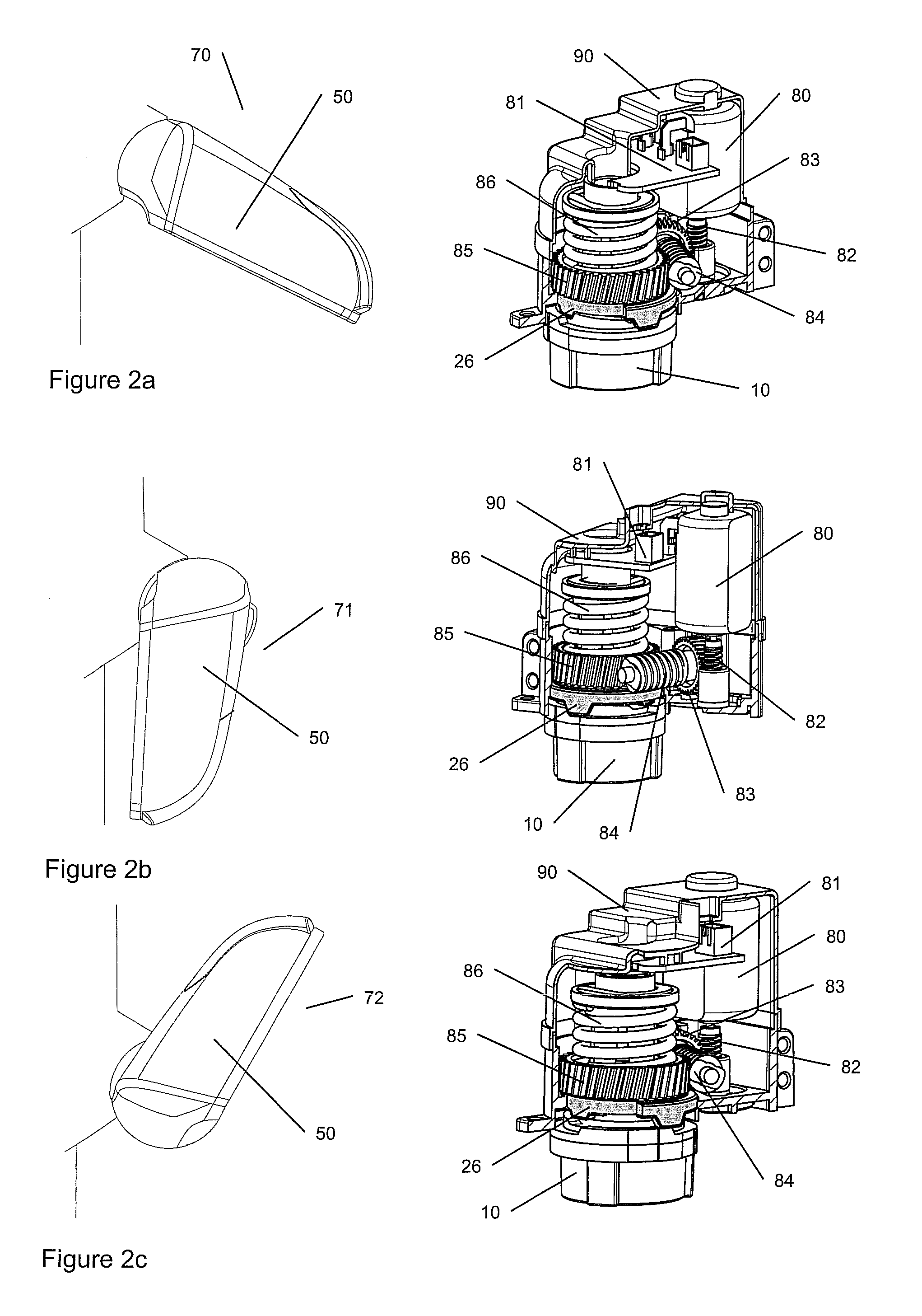
[0037]The shaft 10 which is an axis for rotation to specific position of the minor head 50 is mounted on the base 100 of the wing minor. Details of the shaft are shown in FIG. 7a. The circumference surface of the shaft 10 has shaft projections 13-1, 13-2, 14-1, 14-2 arranged along two radii of regular angle on the shaft flange 12 for controlling fold-in position 71 and neutral position 70 of the power fold module.

[0038]The center of the shaft 10 is open and allows a wiring through the hole. In a preferred embodiment the harness of the minor head passes completely through the hole to connect mirror head with the vehicle...


PUM


Abstract

A hinge construction for a wing mirror unit for a motor vehicle is proposed that comprises a first hinge part for mounting on the motor vehicle and a second hinge part, pivotably connected therewith via a shaft. The second hinge part supports a mirror frame of the wing mirror unit, wherein the shaft is connected with one hinge part and wherein the other hinge part is arranged pivotably about the shaft. The mirror frame has a location guide that corresponds with a location rib of a power fold module that is inserted into the frame.

Description

BACKGROUND ART[0001]The invention is based on a priority patent application EP 09171051 which is hereby incorporated by reference.FIELD OF THE INVENTION[0002]The invention is related to a hinge construction for a wing mirror unit for a motor vehicle that comprises a first hinge part for mounting on the motor vehicle and a second hinge part, pivotably connected therewith via a shaft. The second hinge part supports a mirror frame of the wing mirror unit, wherein the shaft is connected with one hinge part.[0003]More especially the invention provides a solution to fit the powerfold into the mirror frame.[0004]In addition a solution is proposed to decouple motor of powerful efficient from the motor worm that transfers the forces into a wing mirror motion.DESCRIPTION OF THE RELATED ART[0005]This invention relates to a hinge construction, in particular for a wing mirror unit of a motor vehicle, comprising a first hinge part for mounting on a motor vehicle and a second hinge part, pivotably...

Claims


Application Information

Patent Timeline
IPC IPC(8): B60R1/074
CPCB60R1/074
Inventor HWANG, HYOK-JOOYU, II-SUNG
Owner SMR PATENTS S A R L
Why Eureka
Try Eureka