Timing calibration pattern for SLDRAM

a calibration pattern and timing technology, applied in the direction of instruments, coding, generating/distributing signals, etc., can solve the problems of inability to know the calibration process time, inability to accurately sample data, and requiring additional complicated circuitry

Inactive Publication Date: 2005-05-03
ROUND ROCK RES LLC +1
View PDF12 Cites 86 Cited by
  • Summary
  • Abstract
  • Description
  • Claims
  • Application Information

AI Technical Summary

Problems solved by technology

While the timing calibration described above, which is conducted at start-up and reset, has been found to perform adequately in most circumstances, there is a problem in that current SLDRAM devices capture incoming data on both positive and negative going transitions of the clock signals CCLK and DCLK.
Moreover, because the 15-bit pseudo random pattern is repeated during the calibration process, there will be alternating times when it is properly synchronized on the correct clock transition, e.g., positive going, and then improperly synchronized with, e.g., a negative going transition, and there is no mechanism for knowing when the calibration process is completed, whether synchronization has been achieved in the positive or negative going transition of the clock.
Thus, calibration may be achieved in the wrong phase of the clock signal, leading to incorrect sampling of the data during memory access operations, or requiring additional complicated circuitry to ensure that incoming data is synchronized to the proper phase of the clock.
Another weakness of the 15-bit synchronization pattern is associated with how calibration is carried out.
However, only out-of-phase cross talk calibration is achieved for any given data path.

Method used


Image

  • Timing calibration pattern for SLDRAM
  • Timing calibration pattern for SLDRAM
  • Timing calibration pattern for SLDRAM

Examples


Embodiment Construction

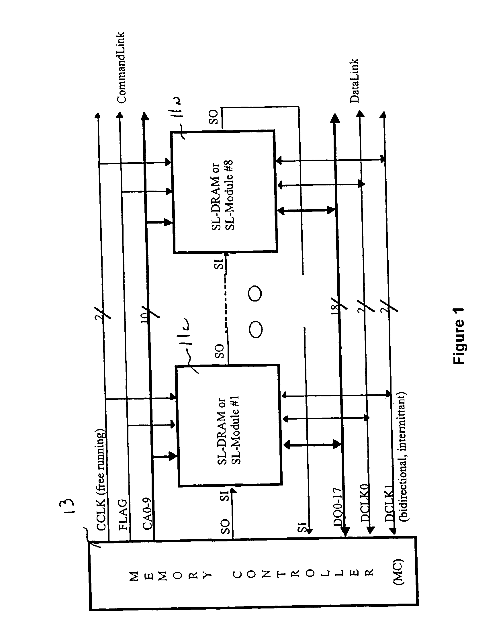
[0020]A SLDRAM system which employs the invention is illustrated in FIG. 1. It includes a plurality of SLDRAM modules 11a . . . 11n which are accessed and controlled by a memory controller 13. Memory controller 13 provides a command link to each of the SLDRAM modules 11a . . . 11n in which includes a clock signal CCLK on inverted and non-inverted clock signal paths, a 1 bit FLAG signal and a 10 bit command bus CAO-9. In addition, SLDRAM input / output signals SO, SI are provided from memory controller is in daisy chain fashion to the SLDRAM modules 11a . . . 11n. In addition, a bi-directional data bus DQO-17 is provided between memory controller 13 and each of the SLDRAM modules 11a . . . 11n, as are bi-directional data clocks DCLKO and DCLK1. The clock DCLKO is used to strobe input / output data into and out of the SLDRAM modules, a process for which the DCLK1 signal path is also intermittently used.

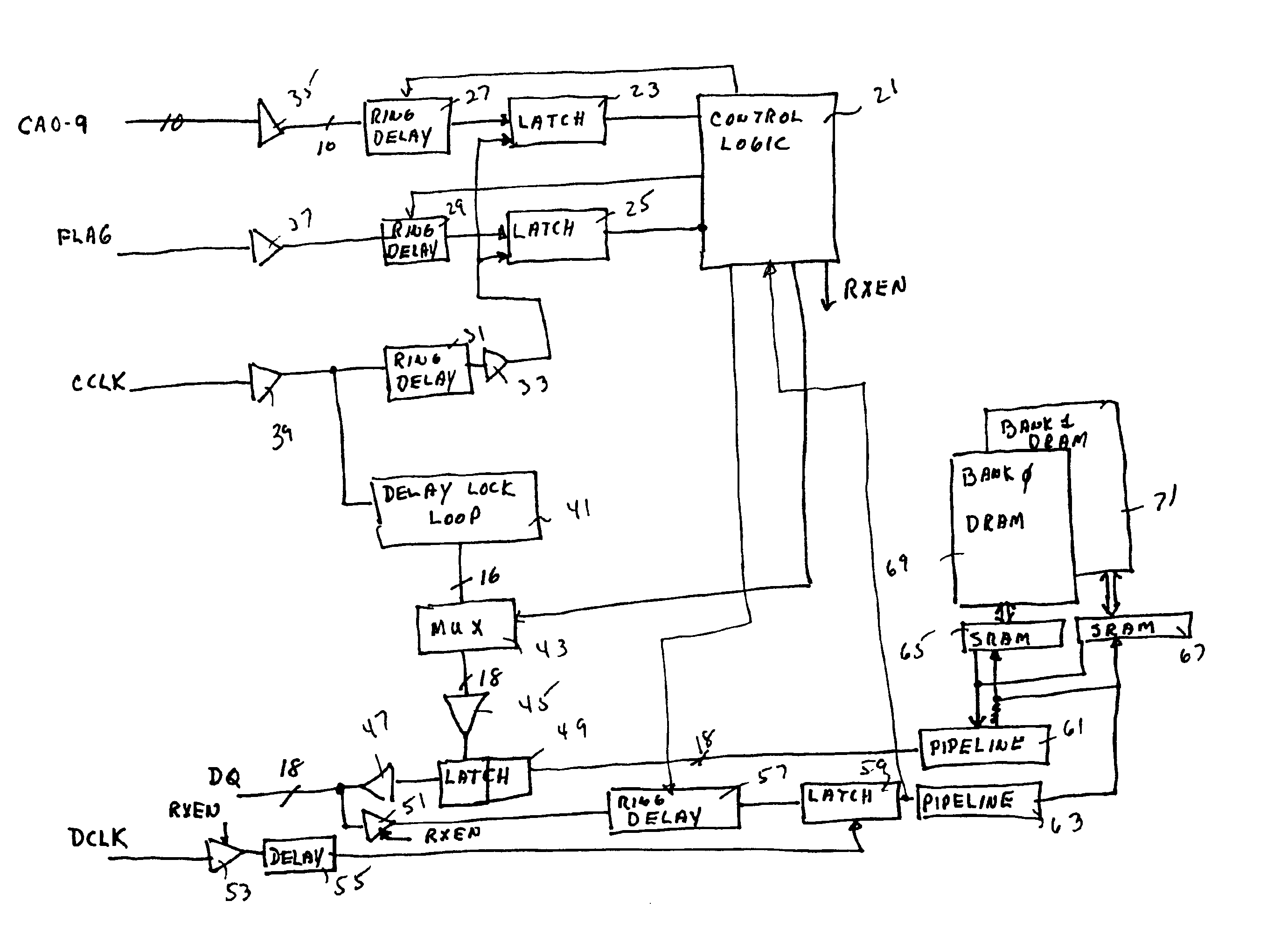
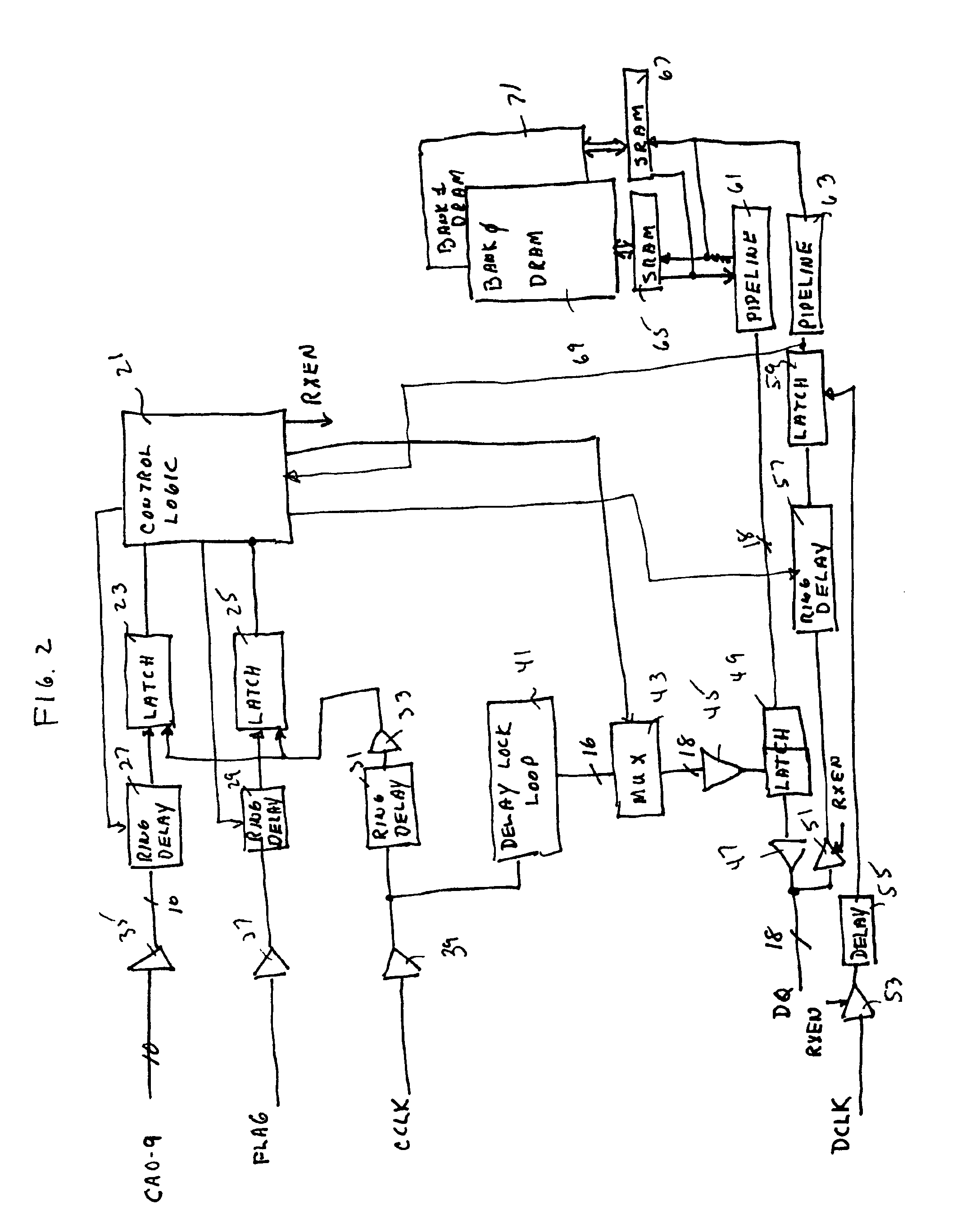
[0021]FIG. 2 illustrates a simplified relevant portion of one of the SLDRAM modules 11a...


PUM

PropertyMeasurementUnit
memory densityaaaaaaaaaa
speedaaaaaaaaaa
phaseaaaaaaaaaa

Abstract

Disclosed is an improved start-up / reset calibration apparatus and method for use in an SLDRAM memory device A 2N bit calibration pattern which is based on a pseudo random sequence is used to calibrate the relative timing of data and a latching clock signal to ensure optimal operation of the memory device. In addition, during calibration of one data path, other nearby data paths may receive in phase, out of phase and / or both in phase and out of phase versions of the calibration pattern so that the data path under calibration is calibrated under conditions which more closely approximate random operating conditions.

Description

FIELD OF THE INVENTION[0001]The present invention relates to an improved binary calibration pattern which is useful for calibrating timing of control and data signals in SLDRAM memory devices.DISCUSSION OF THE RELATED ART[0002]Memory devices are constantly evolving in the directions of faster speed and higher memory density. To this end, dynamic random access memory (DRAM) devices have evolved from simple DRAM devices to EDO to SRAM to DDR SDRAM to SLDRAM, the latter of which is the subject of much current industry interest. SLDRAM has a high sustainable bandwidth, low latency, low power, user upgradability and support for large hierarchical memory applications. It also provides multiple independent banks, fast read / write bus turn-around, and the capability for small fully pipelined burst.[0003]One characteristic of SLDRAM is that it uses both the positive- and negative-going edges of a clock cycle to READ and WRITE data to the memory cells and to receive command and FLAG data from ...

Claims


Application Information

Patent Timeline
Patent Type & Authority Patents(United States)
IPC IPC(8): G11B27/00G11C8/02H04L7/00G11C7/10H03L7/081H04L7/04H04L7/10
CPCG11C7/1072G11C7/222H04L7/043H04L7/10G11C2207/2254H04L7/0041H03L7/0812
Inventor KEETH, BRENTJOHNSON, BRIANLEE, TERRY R.FULLER, PAUL M.
Owner ROUND ROCK RES LLC
Why Eureka
Try Eureka