Sensing system for multiple lumen tubing

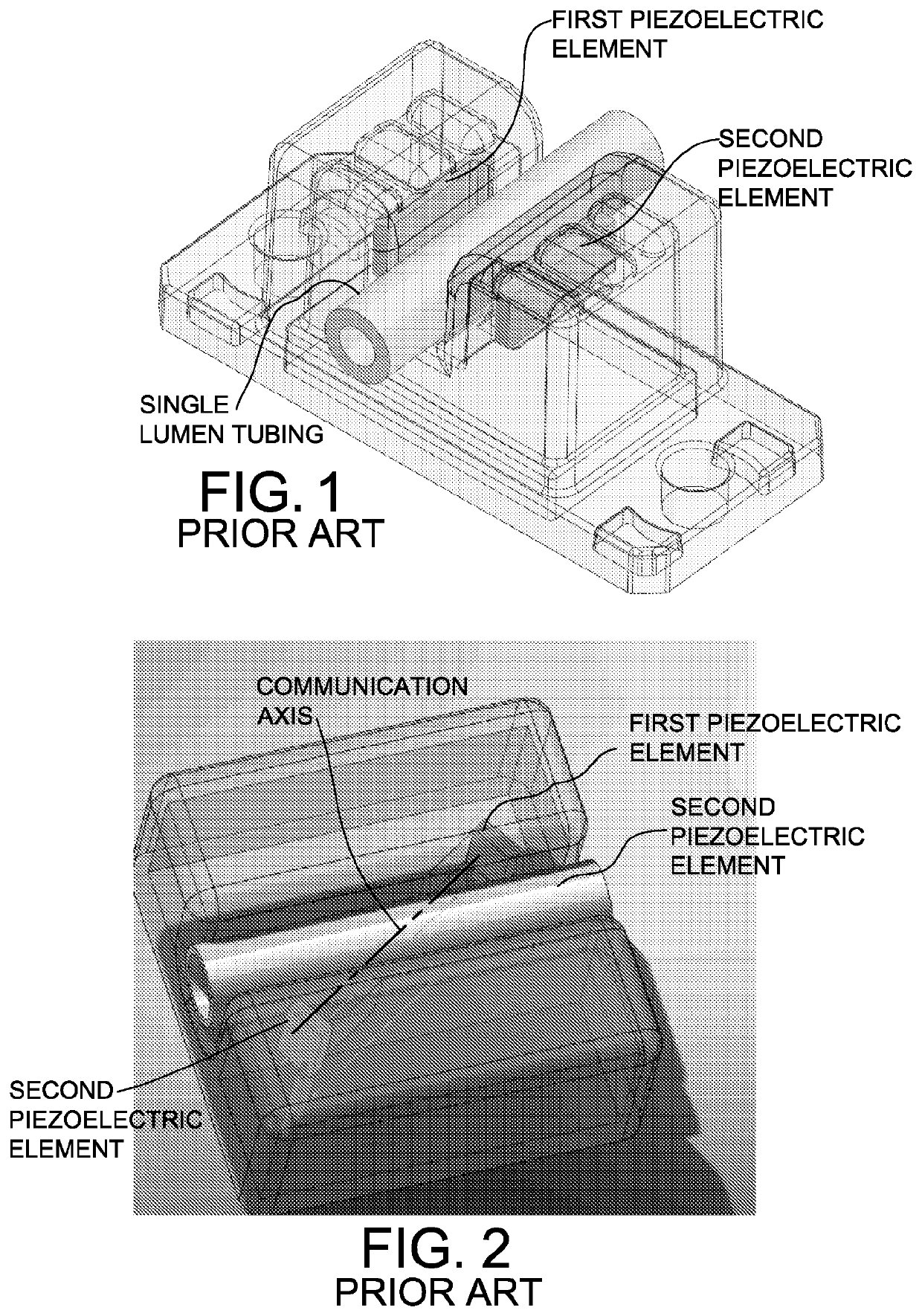
a sensing system and tubing technology, applied in the field of sensing fluid flow within medical tubing, can solve the problems of weakening of the signal generated by the receiving element, single lumen tubing method is not effective for multiple lumen tubing, single lumen tubing method is not effective for multiple, etc., to achieve the effect of maximizing attenuation

Active Publication Date: 2021-08-24
ZEVEX
View PDF19 Cites 0 Cited by
  • Summary
  • Abstract
  • Description
  • Claims
  • Application Information

AI Technical Summary

Benefits of technology

[0006]In one embodiment, the at least one secondary passageway contains a plurality of transmitting elements each transmitting a respective ultrasonic signal across a corresponding one of the plurality of lumens, and the sensing receptacle includes a plurality of receiving elements respectively corresponding to the plurality of transmitting elements. Each of the plurality of receiving elements is arranged to receive the respective ultrasonic signal from a corresponding one of the plurality of transmitting elements after the ultrasonic signal has passed through a corresponding lumen. The plurality of transmitting elements may be arranged within a single secondary passageway, and an acoustic damping member may be arranged between the plurality of transmitting elements to maximize attenuation and stifle propagation of acoustic waves in a direction toward an unassociated lumen.

Problems solved by technology

The large difference in acoustic impedance between liquid flowing in the lumen and an air bubble in the liquid results in reflection and scattering of the acoustic waves, thereby weakening the signal generated by the receiving element.
This single lumen tubing method is not effective for multiple lumen tubing because each lumen cannot be sensed individually.
Here again, the single lumen tubing method is not effective for multiple lumen tubing because each lumen cannot be sensed individually.

Method used


Image

  • Sensing system for multiple lumen tubing
  • Sensing system for multiple lumen tubing
  • Sensing system for multiple lumen tubing

Examples


Embodiment Construction

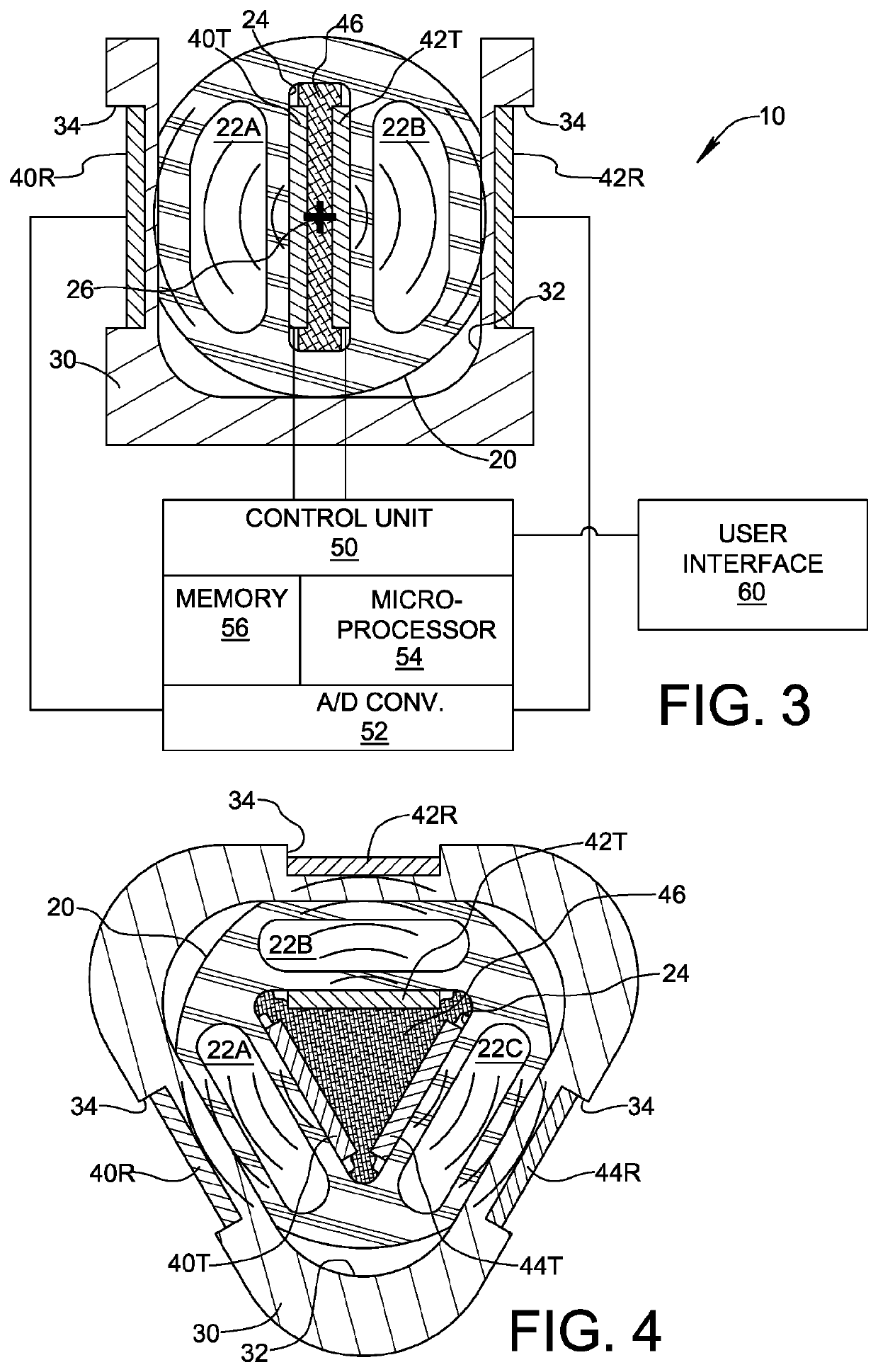
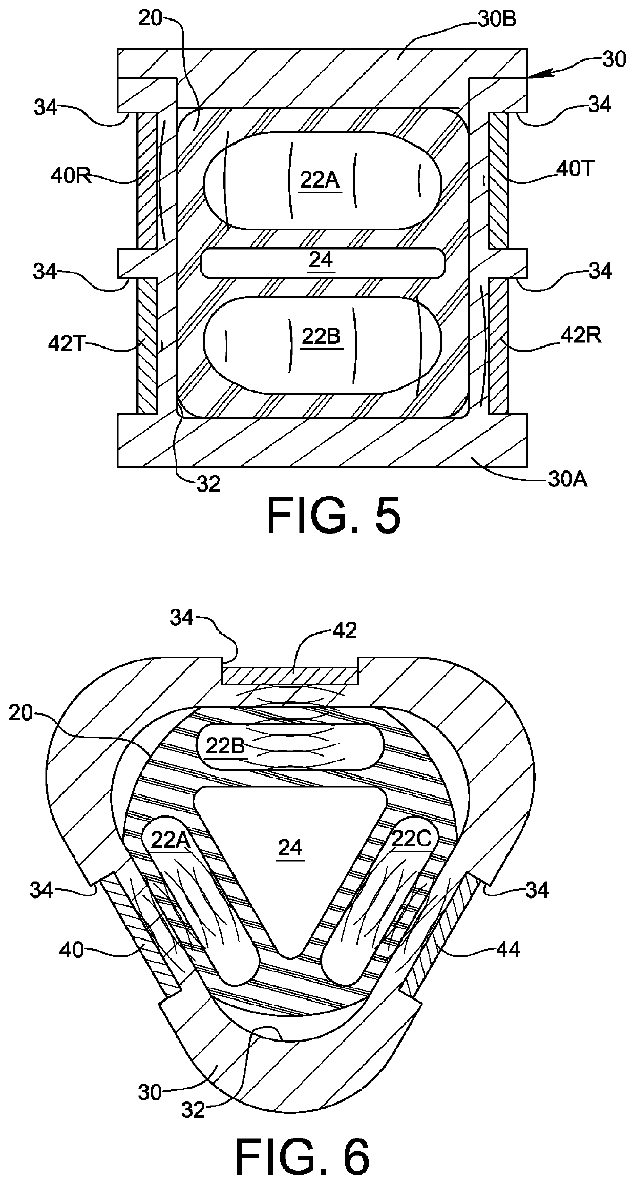
[0017]FIG. 3 depicts a system 10 for sensing fluid flow within respective lumens of multiple lumen tubing 20 according to an embodiment of the present invention. The multiple lumen tubing 20, shown in cross-section in FIG. 3, comprises a plurality of sensed lumens 22A, 22B which may be used as conduits for flowing fluids. The plurality of sensed lumens 22A, 22B may have different respective cross-sectional shapes and sizes, or may have identical dimensions. The multiple lumen tubing 20 may further comprise a secondary passageway 24 for purposes described below. As may be understood, multiple lumen tubing 20 extends longitudinally into and out of the plane of drawing FIG. 3 along a central longitudinal axis 26, and may be flexible to define a non-linear flow path.

[0018]System 10 further comprises a sensing receptacle 30 defining a channel or other type of passage 32 sized to receive a lengthwise portion of multiple lumen tubing 20. In FIG. 3, sensing receptacle 30 has an open U-shape...


PUM


Abstract

A multi-lumen sensing system (10) includes medical tubing (20) having a plurality of lumens (22A, 22B) and at least one secondary passageway (24) extending in an axial direction of the medical tubing, wherein the secondary passageway is between the plurality of lumens. The multi-lumen sensing system may include a sensing receptacle (30) defining a channel (32) in which a lengthwise portion of the medical tubing is received. A plurality of ultrasonic transmitting elements (40T, 42T) may be arranged within the secondary passageway of the medical tubing or as part of the sensing receptacle for transmitting respective ultrasonic signals across the lumens to a corresponding plurality of ultrasonic receiving elements (40R, 42R) of the sensing receptacle. Alternatively, the sensing receptacle may include a plurality of ultrasonic transmitting and receiving elements (40, 42, 44) transmitting respective signals across the lumens for return reflection at an interface of the secondary passageway.

Description

FIELD OF THE INVENTION[0001]The invention relates to sensing fluid flow within medical tubing, specifically medical tubing having multiple lumens.BACKGROUND OF THE INVENTION[0002]Medical tubing is manufactured by extrusion or co-extrusion of one or more biomedical grade polymers in a variety of cross-sectional shapes and with multiple lumens of various cross-sectional shapes and sizes. Multiple lumen tubing can be found in various medical devices including catheters, extension lines, transfusion devices, and monitoring devices. Multiple lumen tubing provides a plurality of conduits for efficiently transporting various fluids, including medications and contrast agents, into and out of the body. Multiple lumen tubing is also used to accommodate a guide wire and electrical wiring for mechanically positioning and providing power to diagnostic and therapeutic devices in the body.[0003]In some medical applications, it is important to detect the presence and size of constituents carried by...

Claims


Application Information

Patent Timeline
Patent Type & Authority Patents(United States)
IPC IPC(8): A61M5/168A61B5/15A61M39/08A61M5/142A61M1/36A61M37/00
CPCA61M5/16886A61B5/15A61M5/142A61M5/168A61M39/08A61B5/15003A61B5/150946A61M1/3626A61M37/00A61M2039/082A61M2205/33
Inventor PIERCE, NATECLAYTON, LARRYRILEY, TIMOTHY
Owner ZEVEX
Why Eureka
Try Eureka