High transmittance optical windows and method of constructing the same

a technology of optical windows and high transmittance, applied in the field of transparent optical windows, can solve the problems of reducing the transmittance of optical windows through glass, sapphire and quartz windows, limiting the reflection loss of fresnel, and becoming quite substantial for off-angle light incidence, etc., to achieve the effect of maximizing the transmittance of optical windows, reducing reflection losses, and increasing transmittan

Inactive Publication Date: 2011-07-14
MAGNOLIA OPTICAL TECH +1
View PDF10 Cites 71 Cited by
  • Summary
  • Abstract
  • Description
  • Claims
  • Application Information

AI Technical Summary

Benefits of technology

[0011]This invention overcomes the disadvantages of the prior art by providing antireflection structures and a method of manufacturing the antireflection structures to increase the transmittance through a variety of different optical windows for a variety of applications. The various illustrative embodiments reduce reflection losses, thus maximizing transmittance through optical windows. The various illustrative embodiments utilize multiple layer optical coatings in which the refractive index is varied between that of the window material and air in discrete steps. It is possible to design antireflection (AR) coatings that, due to interference effects, have a lower reflectivity than a continuously graded AR coating. In one embodiment, the optical antireflection coating comprised of at least two layers, up to any plurality of layers, which have a similar chemical composition but a different porosity and thus a different refractive index. In another embodiment, the optical antireflection coating contains (i) at least one layer of the AR coating comprising a single dense material, (ii) at least one layer of the AR coating comprising a solid solution of two different dense materials (that is a mixture of two dense materials), and (iii) at least one layer of the AR coating comprising a porous material. In yet another embodiment, a pore-closure layer is employed that covers the top surface and prevents moisture, or particles, from infiltrating the porous film. The pore-closure layer is very thin (much smaller than λ) so as to be applied without influencing the reflectivity of the AR coating. More particularly, the pore closure layer is constructed and arranged to avoid negatively affecting the reflectivity.
[0013]In another illustrative embodiment, a plurality of antireflection layers of transparent refractive thin film are deposited on the front, sun-facing surface of a photovoltaic device. The purpose of the antireflection layers is to maximize the number of incident photons that are directed into the active region of an underlying semiconductor solar cell device. The antireflection structure is formed of multiple layers of optical thin film material on top of a transparent cover glass, while having an index of refraction intermediate between that of the glass and air. In the illustrative embodiment, the profile is characterized by a step-graded profile that may or may not follow a quintic profile to provide maximum photon transmission through the antireflection layers. The exact thickness and index of refraction of each of the layers in the antireflection layer can be adjusted to further minimize reflection losses over a broad spectrum of photon wavelengths and angles of incidence. The antireflection coating can be built using a variety of different materials, either in combination or with various degrees of porosity, including but not limited to, SiO2, TiO2, Si3N4, BaF2, CdTe, ITO or other TCO materials, and diamond like carbon materials. In a specific embodiment, the index of refraction in the topmost coating is varied from 1.5 to 1.1 over three steps, with the plurality of deposited layers defining approximately 192 nm of porous SiO2 (n˜1.36), approximately 179 nm of porous SiO2(n˜1.19), and approximately 260 nm of porous SiO2(n˜1.10).

Problems solved by technology

Because these materials have very low absorption coefficients over a wide range of photon energies, optical transmittance through glass, sapphire, and quartz windows is typically limited by reflection losses.
Although Fresnel reflection losses are typically relatively low at normal incidence, they can become quite substantial for off-angle light incidence.
This reflection is undesirable in many applications as it can degrade the efficiency of the underlying device (e.g. efficiency of a solar photovoltaic cell), reduce signal-to-noise ratio (e.g. in a photodetector), and cause glare (e.g. from LCD screens, computer monitors, and televisions).
Often due to unavailability of materials with the desired, exact value of the refractive index, the performance of such λ / 4 AR coatings deviates from the optimum.
There is no conventional inorganic material that has such a low refractive index.
Also, fundamentally, these single-layer λ / 4 AR coatings can minimize reflection only for one specific wavelength at normal incidence and they are inherently unable to exhibit spectrally broadband reduction in reflectance over wide range of angles-of-incidence.
Optimization of multi-layer AR coatings is a difficult challenge because of the extremely large and complex dimensional space of possible solutions.
Analytical methods to optimize AR coatings are not feasible due to the complexity of the problem.
Until recently, however, the unavailability of materials with desired refractive indices, particularly materials with very low refractive indices below n=1.2, prevented the implementation of high-performance step graded refractive index designs.

Method used


Image

  • High transmittance optical windows and method of constructing the same
  • High transmittance optical windows and method of constructing the same
  • High transmittance optical windows and method of constructing the same

Examples


Embodiment Construction

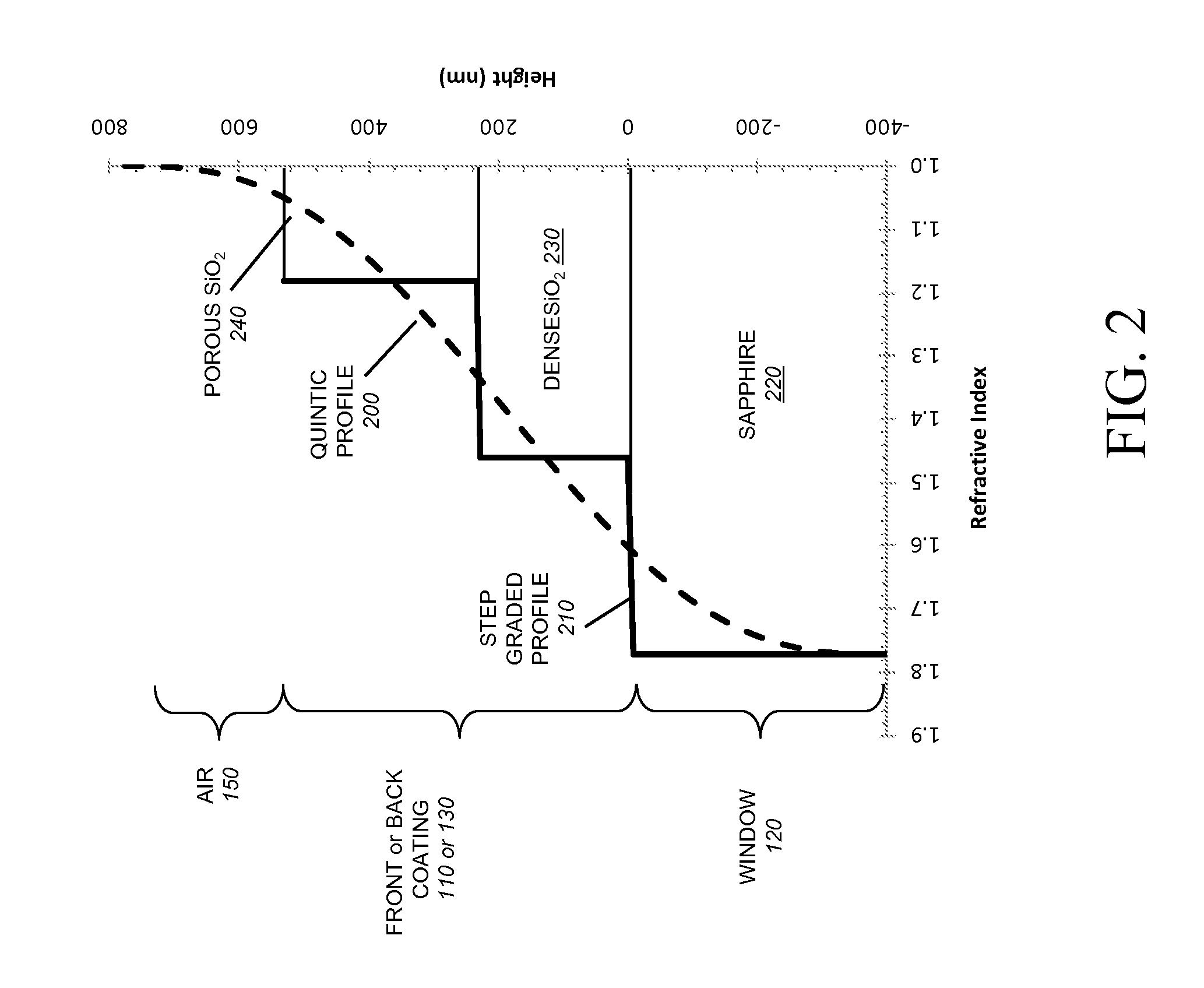
[0024]Ultra-high, broadband transmittance through coated glass windows is demonstrated over a wide range of incident angles. The measured improvements in transmittance result from coating the windows with materials consisting of porous nanorods. The use of porous nano-materials fabricated by, for example, oblique-angle deposition, enables a tunable refractive index, flexibility in choice of material, simplicity of a physical vapor deposition process, and the ability to optimize the coating for any substrate-ambient material system. A multi-layer coating adapted for a glass substrate, is fabricated and characterized as described below. For multi-layer AR coatings, according to an illustrative embodiment, the refractive index of the layers is step-graded (i.e. decreased in discrete steps), from the substrate value, 1.46, to a value of 1.18, according to the various illustrative embodiments.

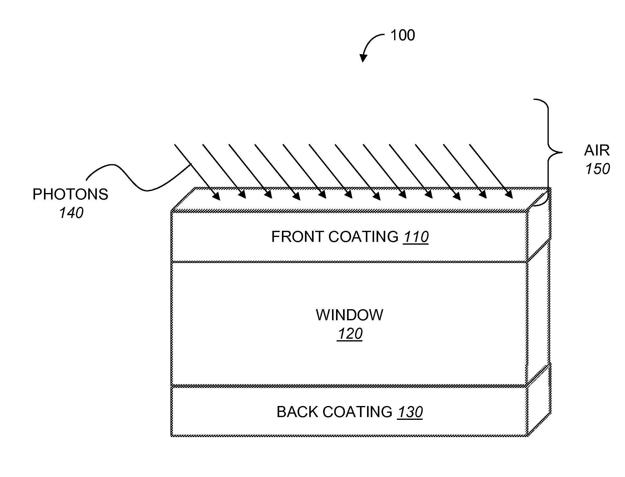
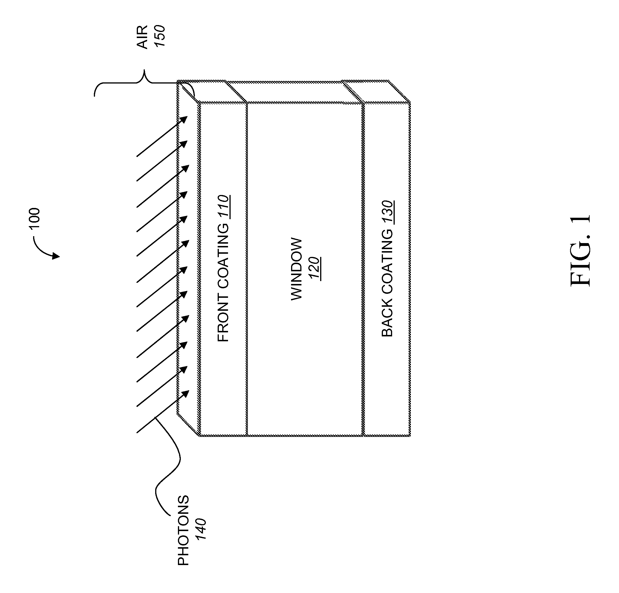
[0025]FIG. 1 details a cross-sectional view illustrating a high transmittance window structure 1...


PUM


Abstract

Designs for ultra-high, broadband transmittance through windows over a wide range of incident angles are disclosed. The improvements in transmittance result from coating the windows with a new class of materials consisting of porous nanorods. A high transmittance optical window comprises a transparent substrate coated on one or both sides with a multiple layer coating. Each multiple layer coating includes optical films with a refractive index intermediate between the refractive index of the transparent substrate and air. The optical coatings are applied using an oblique-angle deposition material synthesis technique. The coating can be performed by depositing porous SiO2 layers using oblique angle deposition. The high transmittance window coated with the multiple layer coating exhibits reduced reflectance and improved transmittance, as compared to an uncoated transparent substrate.

Description

RELATED APPLICATIONS[0001]This application claims the benefit of co-pending U.S. Provisional Patent Application Ser. No. 61 / 293,469, filed on Jan. 8, 2010 entitled EFFICIENT SOLAR CELL EMPLOYING MULTIPLE ENERGY-GAP LAYERS AND LIGHT-SCATTERING STRUCTURES AND METHODS FOR CONSTRUCTING THE SAME, which is expressly incorporated herein by reference.GOVERNMENT SUPPORT[0002]This invention was supported in part by Small Business Innovative Research (SBIR) contract # W31P4Q-08-C-0300 from the Defense Advanced Research Projects Agency (DARPA) to Magnolia Optical Technologies, Inc., 52 B Cummings Park, Suite 314, Woburn, Mass. 01801. The government may have certain rights in this invention.FIELD OF THE INVENTION[0003]This invention relates to transparent optical windows for detectors, sensors, and other optical devices; and to semiconductor-based photovoltaic energy converters, also known as “solar cells,” and to the design and fabrication of the same.BACKGROUND OF THE INVENTION[0004]Transparen...

Claims


Application Information

Patent Timeline
Patent Type & Authority Applications(United States)
IPC IPC(8): H01L31/0232G02B1/10H01L31/18
CPCG02B1/115H01L31/02165H01L31/02168Y02E10/50Y02E10/544H01L31/035263H01L31/065H01L31/0725H01L31/03046Y02E10/52H01L31/0543H01L31/0547H01L31/0232H01L31/0445H01L31/056H01L31/0203H01L31/022425H01L31/035236H01L31/0735H01L31/184H01L31/1844H01L31/022475H01L31/048H01L31/1884
Inventor WELSER, ROGER E.SOOD, ASHOK K.POXSON, DAVID J.CHHAJED, SAMEERMONT, FRANK W.CHO, JAEHEESCHUBERT, E. FRED
Owner MAGNOLIA OPTICAL TECH
Why Eureka
Try Eureka