Narrow frame display panel and display device

A display panel and display device technology, which is applied in nonlinear optics, instruments, optics, etc., can solve the problems of increasing the thickness of the display, and achieve the effects of increasing the screen ratio, ensuring optical quality, and preventing specular reflection

Inactive Publication Date: 2018-02-23
WUHAN CHINA STAR OPTOELECTRONICS TECH CO LTD
View PDF8 Cites 67 Cited by
  • Summary
  • Abstract
  • Description
  • Claims
  • Application Information

AI Technical Summary

Problems solved by technology

For example, the chip (IC) is bound (bonding) to the FPC (Flexible Printed Circuit, that is, the flexible circuit board), so that the original space occupied by the panel for bonding the chip can be saved, and a narrower lower frame can be achieved. For the purpose, when the entire FPC is bent, the chip is located on the lower surface of the backlight module and is facing the reflector. Since the chip is formed as a protrusion with a certain height, it is necessary to add a spacer to avoid direct contact with the reflector. Cause damage to both. However, the chip is a heat source. If it is close to the reflector, it will easily cause the optical quality of the backlight module. At the same time, due to the existence of the spacer, the thickness of the display will also increase a lot.

Method used


Image

  • Narrow frame display panel and display device
  • Narrow frame display panel and display device

Examples


Embodiment Construction

[0018] In order to make the object, technical solution and advantages of the present invention more clear, the present invention will be further described in detail below in conjunction with the accompanying drawings and embodiments. It should be understood that the specific embodiments described here are only used to explain the present invention, not to limit the present invention.

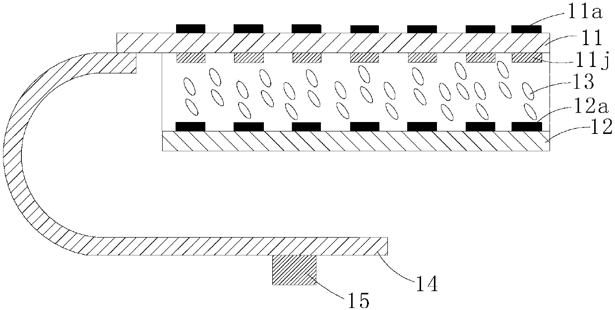
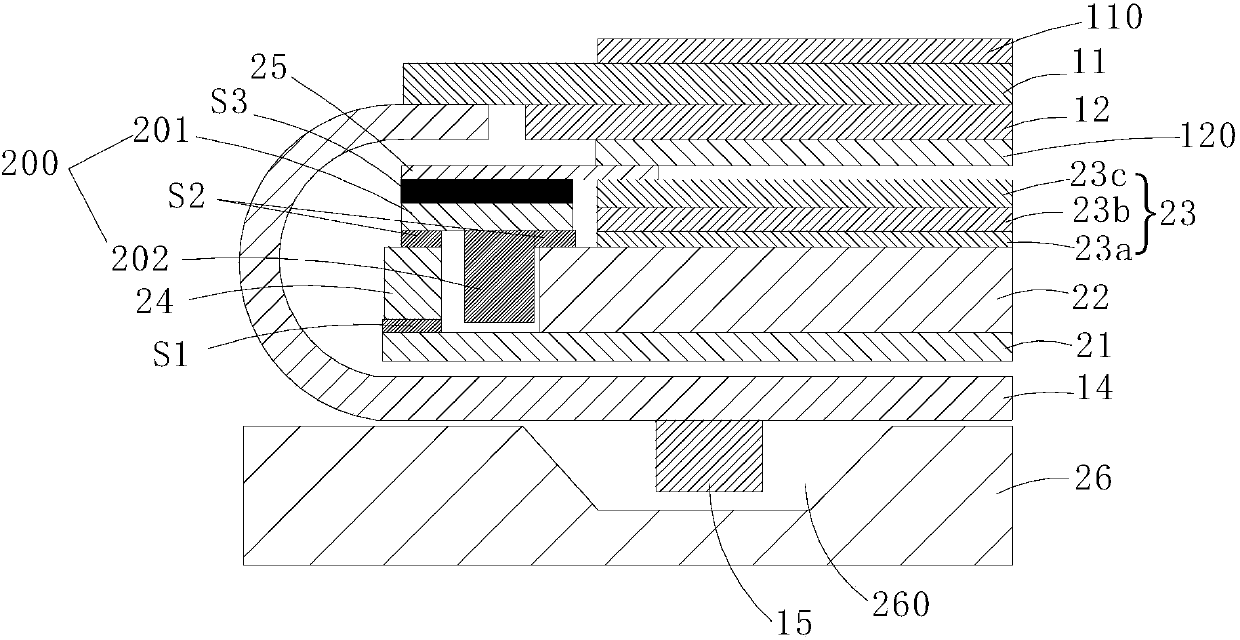
[0019] refer to figure 1 with figure 2 The narrow frame display panel of the embodiment of the present invention mainly includes an array substrate 11 and a color filter substrate 12 arranged opposite to each other, a liquid crystal 13 filled between the array substrate 11 and the color filter substrate 12, a flexible circuit board 14 and a driving chip 15, and The difference of the conventional display panel is that in this embodiment, the side where the array substrate 11 is located is the light output surface, and the backlight source receives light from the side where the color filter subs...


PUM


Abstract

The invention discloses a narrow frame display panel. The narrow frame display panel comprises an array substrate, a color film substrate, a liquid crystal filled between the color film substrate andthe array substrate, a flexible printed circuit board and a driving chip. The side where the array substrate is positioned is a light-emitting surface; one end of the array substrate is a binding end;one end of the flexible printed circuit board is bound on the surface, facing the color film substrate, of the binding end; the driving chip is bound at the other end of the flexible printed circuitboard; after the flexible printed circuit board is bent back to the light-emitting surface, the flexible printed circuit board is arranged opposite to the color film substrate; the driving chip is positioned on one surface, deviating from the color film substrate, on the flexible printed circuit board. The invention also discloses a display device. By binding one end of the flexible printed circuit board on the surface, facing the color film substrate, of the binding end and binding the other end of the flexible printed circuit board with the driving chip, the width of the frame can be reduced; the driving chip is far from a reflector plate of a backlight module, so that the optical quality is ensured and the thickness of the display device cannot be increased; meanwhile, a black shieldinglayer on the outer surface of the array substrate also can prevent specular reflection.

Description

technical field [0001] The present invention relates to the field of display technology, in particular to a narrow frame display panel and a display device. Background technique [0002] At present, the popularity of full-screen mobile phones is getting higher and higher, and screens with high screen-to-body ratios are becoming more and more popular. As a result, many narrow bezel solutions have been created, mainly for the left and right bezels, but for mobile phones, the lower bezels have always been improved to increase the screen-to-body ratio. It's a big issue. The so-called screen-to-body ratio refers to the ratio of the screen area to the overall machine area. A higher screen-to-body ratio can bring users a better visual experience. Flexible OLED displays are currently a key element for achieving hyperboloid designs. With the maturity of flexible OLED technology, more innovations and changes will inevitably occur in the appearance design and physical form of future m...

Claims


Application Information

Patent Timeline
Patent Type & Authority Applications(China)
IPC IPC(8): G02F1/1333G02F1/1362
CPCG02F1/1333G02F1/136209
Inventor 崔宏青李得俊龙柏华宋文庆
Owner WUHAN CHINA STAR OPTOELECTRONICS TECH CO LTD
Why Eureka
Try Eureka