Nano-structured thin film with reduced light reflection
- Summary
- Abstract
- Description
- Claims
- Application Information
AI Technical Summary
Benefits of technology
Problems solved by technology
Method used
Image
Examples
examples
A. Synthesis of Organically Modified Nanoparticles
[0081] In this example, a solution comprising a silane coupling agent and a first solvent was added slowly to a nanoparticle dispersion in a second solvent at a certain temperature at which the first solvent with a lower boiling point is distilled out gradually, thereby yielding an organically modified nanoparticle dispersion in the second solvent. In particular, methacryloxypropyl dimethylethoxysilane-functionalized elongated SiO2 nanoparticles in propyl acetate was prepared as follows.
[0082] A dispersion comprising 100 grams of 20 wt % elongated SiO2 nanoparticle (10 to 50 nm average diameter) dispersed in methanol that was purchased from Nissan Chemicals, known as MA-ST-UP, was charged into a 500 ml three-neck round bottom flask equipped with an addition funnel, distillation condenser, and a magnetic stir bar. When the dispersion started refluxing, a solution containing 4.5 grams of methacryloxypropyldimethyl ethoxysilane (Aldr...
examples 1-4
[0084] A UV-curable monomer in a solvent was placed on a small-prop stirring device. To this mixture was added photo-initiator. After stirring for certain period of time, organically modified nanoparticles dispersed in another solvent was added drop wise to the mix. The resulting mixture has sufficiently low viscosity that it could be micro pumped through a moving X-hopper and applied to plastic film substrate. The coated substrate was dried and expose to a UV lamp to complete curing. The thickness of the coated film can be controlled by different experimental factors such as solvent, coverage, concentration, and so on, and can be measured by transmission electron microscopy (TEM).
[0085] In particular, for Example 1, a composition comprising 11.37 grams of a 6.94% solids solution of SARTOMER CN968 (UV curable oligomer) in n-propylacetate was placed on a small prop-stirring device at 1200 rpm. To this mixture was added 0.316 grams of a 5% solution of CIBA IRGACURE 184 photo-initiato...
examples 9 , 10
EXAMPLES 9, 10, and 11
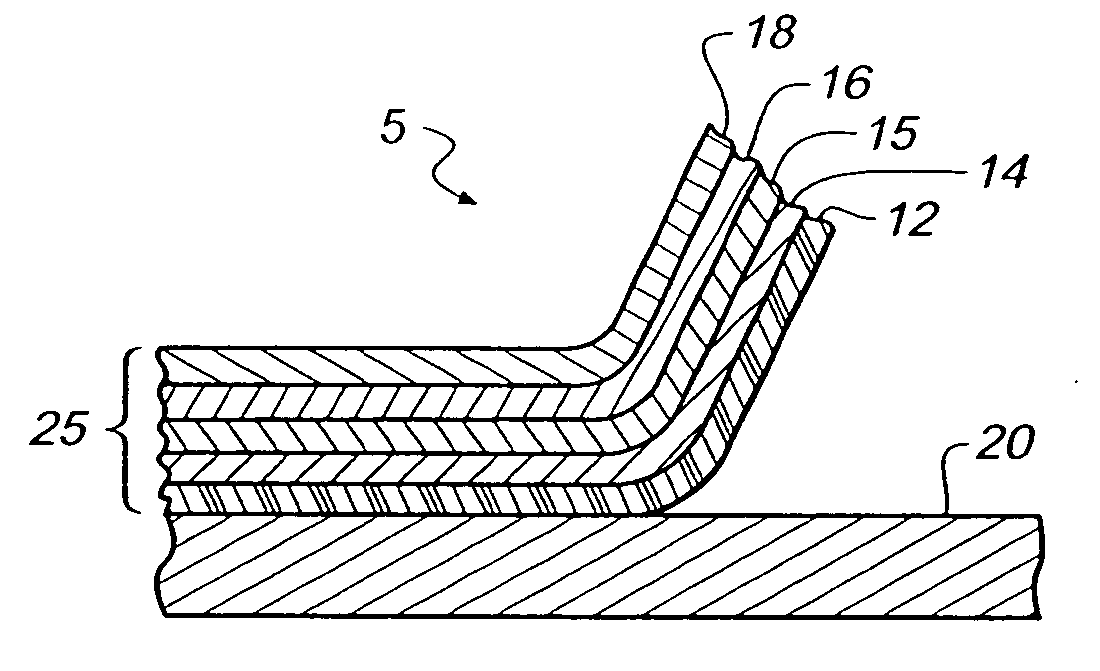
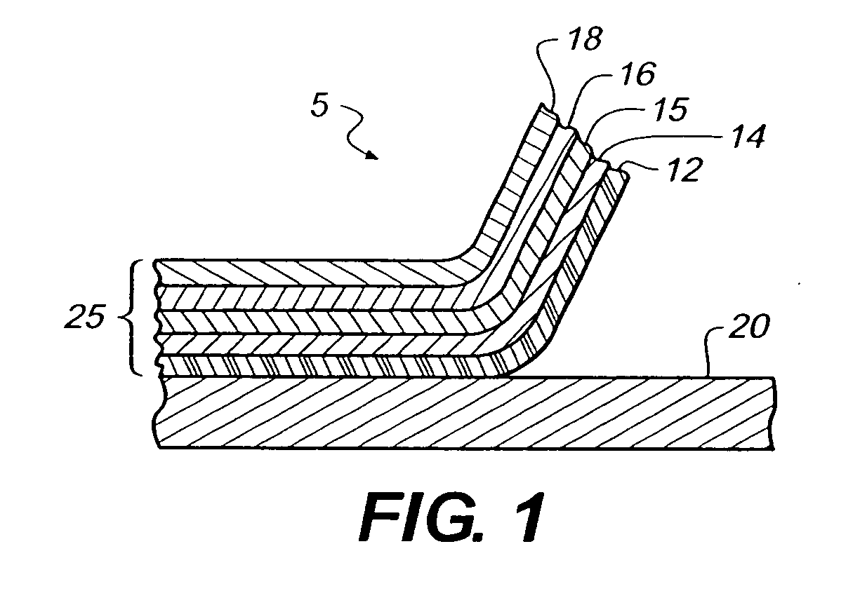
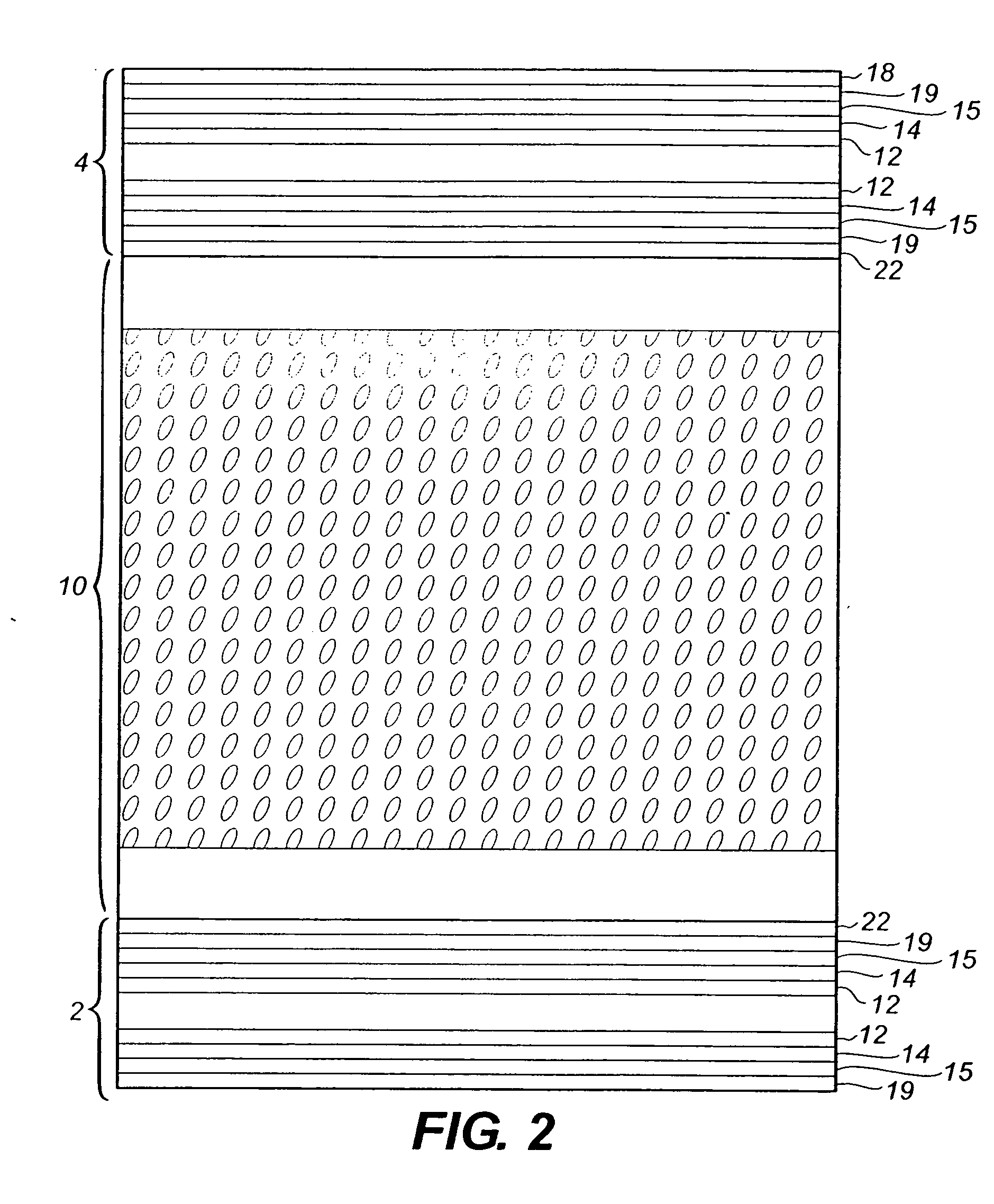
[0095] This Example illustrates the preparation of a nano-structured anti-reflective film comprising organically modified elongated nanoparticles of SiO2 and LUMIFLON fluorinated polymer.
[0096] For Example 9, a composition comprising 11.62 grams of a 6.8% solids solution of LUMIFLON polymer in n-propylacetate was placed on small prop stirring device at 1200 rpm. Then, 3.38 grams of a 10% dispersion of modified elongated silica in n-propylacetate was added drop wise to the mix. The resulting 7.5% solids mixture was micro pumped through a moving X-hopper and applied at 1.5 cc / ft2 (16.15 cc / m2) to a static held cellulose triacetate substrate. The coated substrate was dried in an 85° F. (29.4° C.) laminar-flow hood for 5 min.
[0097] For Example 10, the anti-reflection layer was generated in a similar way to that in Example 9 except using different solid coverage.
[0098] For Comparative Example 11, a coated layer was generated in a similar way to that in Example 9 ...
PUM
| Property | Measurement | Unit |
|---|---|---|
| Percent by mass | aaaaa | aaaaa |
| Percent by mass | aaaaa | aaaaa |
| Thickness | aaaaa | aaaaa |
Abstract
Description
Claims
Application Information
 - R&D
- Intellectual Property
- Life Sciences
- Materials
- Tech Scout
- Unparalleled Data Quality
- Higher Quality Content
- 60% Fewer Hallucinations
Browse by: Latest US Patents, China's latest patents, Technical Efficacy Thesaurus, Application Domain, Technology Topic, Popular Technical Reports.
© 2025 PatSnap. All rights reserved.Legal|Privacy policy|Modern Slavery Act Transparency Statement|Sitemap|About US| Contact US: help@patsnap.com


