Medical implant preform produced using an inside out flipping method

Pending Publication Date: 2021-03-25
XELTIS AG
View PDF1 Cites 0 Cited by
  • Summary
  • Abstract
  • Description
  • Claims
  • Application Information

AI Technical Summary

Benefits of technology

[0008]In a specific example, the mandrel distinguishes at least one convex area. As such the inside-out flipped preform distinguishes at least one concave area reflecting the inverse of the at least one convex area of the mandrel. More generally speaking in yet another example, the mandrel distinguishes at least one three-dimensional shaped area. As such the inside-out flipped preform distinguishes at least one three-dimensional shaped area reflecting the inverse shaped area of the at least one three-dimensional shaped area of the mandrel. In still another example, the ma

Problems solved by technology

Both of these techniques have no effect on the material distribution within the leaflet.
While these conventional techniques may help to improve the performance of the valve, they will do nothing to decrease the stre

Method used


Image

  • Medical implant preform produced using an inside out flipping method
  • Medical implant preform produced using an inside out flipping method
  • Medical implant preform produced using an inside out flipping method

Examples


Example

Example 1

State-of-Art

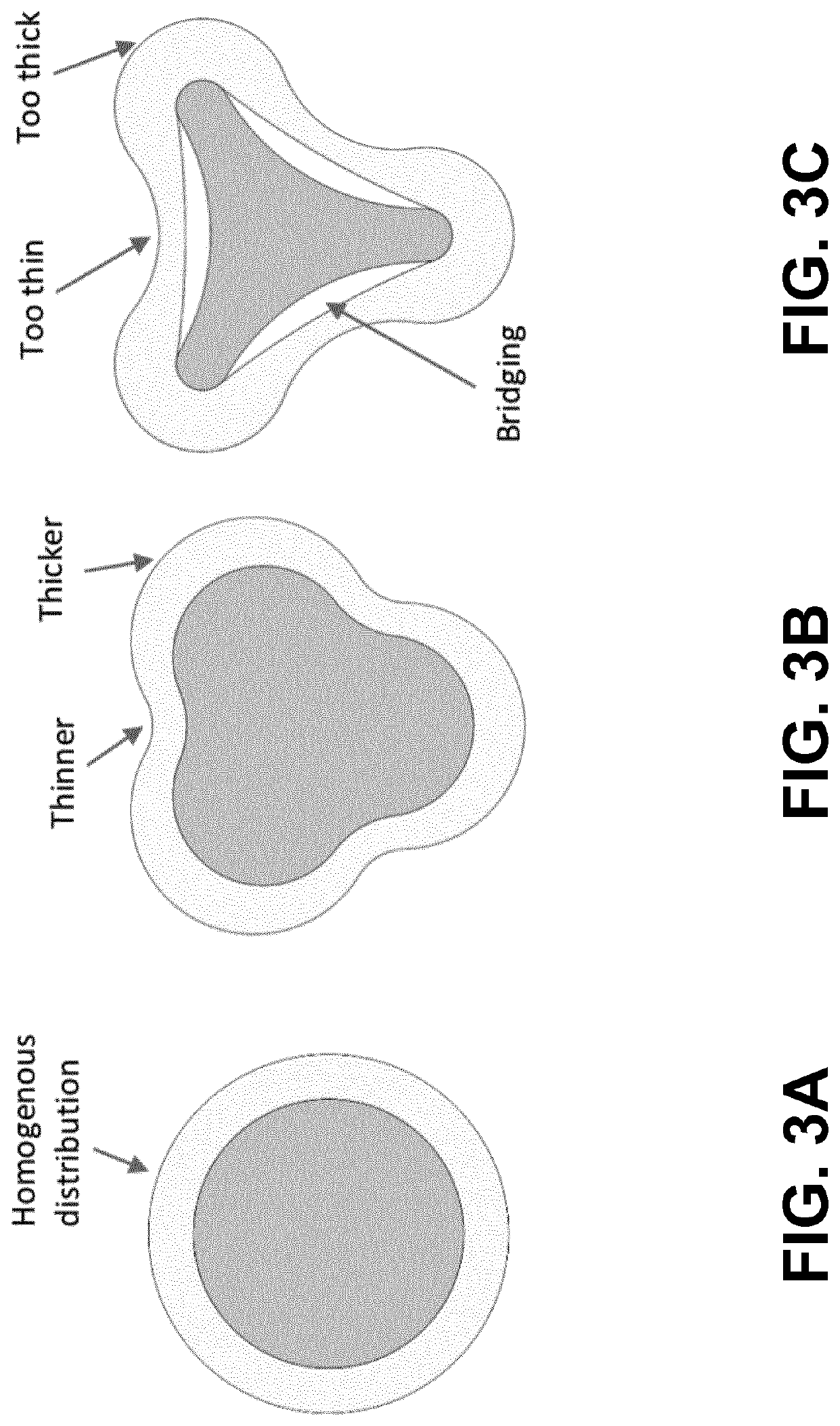
[0032]A preform with a geometry that distinguishes a number of concave surfaces is desired. In a state-of-art example the outer geometry of the mandrel (FIG. 6A) would match the desired inside geometry of the preform. A preform produced on this mandrel would exhibit a number of problems associated with electrospinning on complex geometries. Spinning on this mandrel would yield a preform similar to be one as shown in FIG. 6B (left). The preform would have a varying thickness distribution and show areas with bridging, where the preform will no longer be attached to the mandrel (FIG. 6B, right).

Flipping Inside Out

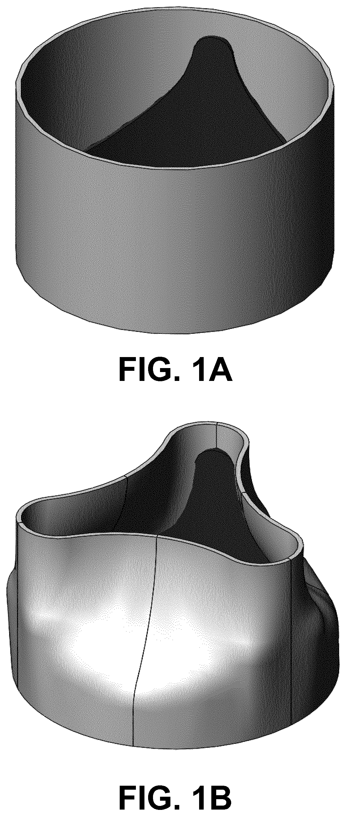
[0033]To produce the same desired preform using the method of this invention, a mandrel with the inverse geometry is used (FIG. 7A). The mandrel distinguishes essentially convex surfaces, resulting in significantly less problems during the electrospinning process; a complex shape with mainly convex shapes and only very limited concave areas. In this embodi...

Example

Example 2

[0036]In the example of FIGS. 8A-B, the mandrel shown in FIG. 8A distinguishes a complex shape with mainly convex shapes and only very limited concave areas. In this example the mandrel and resulting preform are not uniformly formed along the whole length as shown, but shows a variation of the shape along its axis. FIG. 8B (left) is the preform that is formed using the mandrel (FIG. 8A). FIG. 8B (right) is the preform after the preform in FIG. 8B (left) is flipped inside-out. These tubular preforms could be advantageous in cases where the second end should stay open, e.g. for the production of transcatheter valves.

Example

Example 3

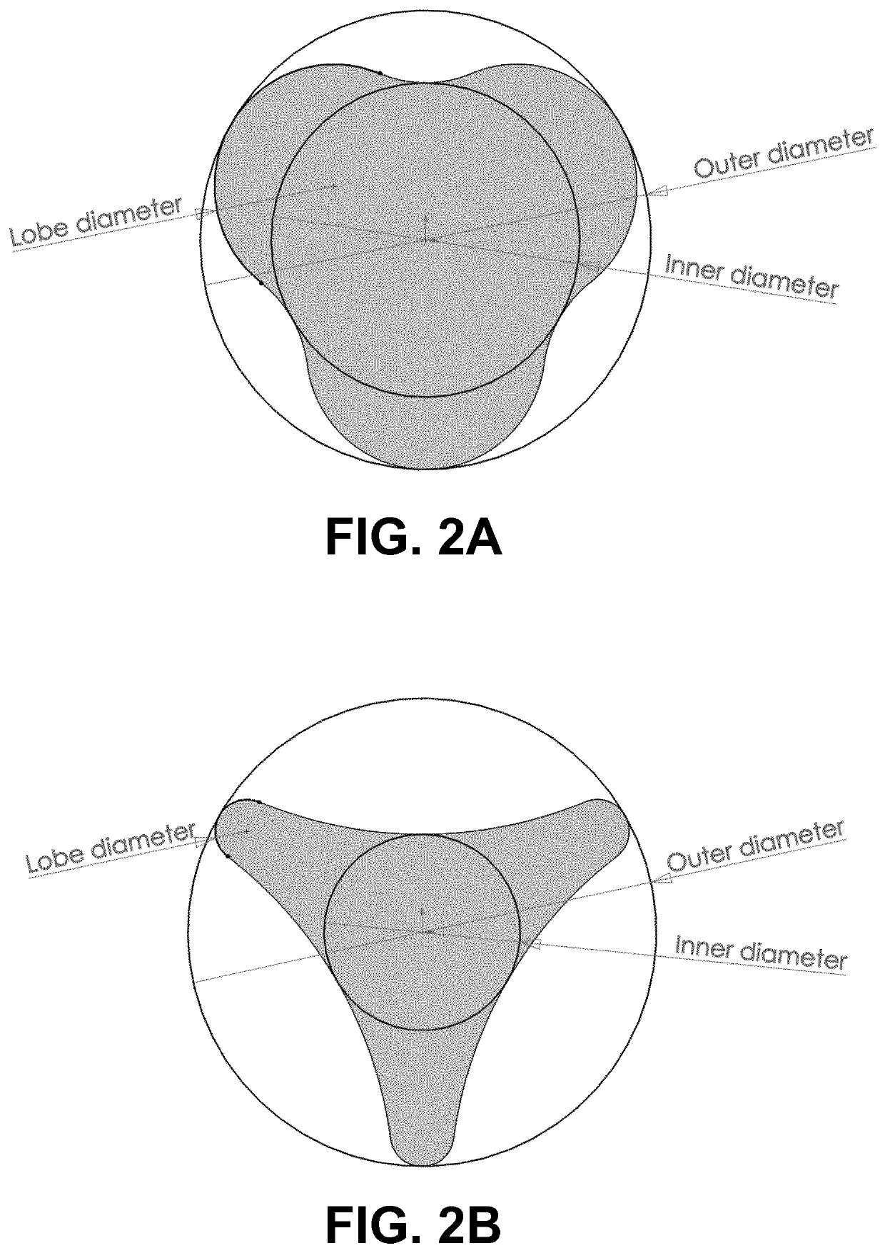
[0037]In the example of FIGS. 9A-B, the mandrel shown in FIG. 9A distinguishes a complex shape with mainly convex shapes and only very limited concave areas. In this example, the mandrel and the resulting preform distinguishes a complex shape with mainly convex shapes and only very local concave areas. In this example, the mandrel has local lobes attached to the cylindrical base. These lobed sections have mainly convex shapes and only very limited concave areas. FIG. 9B (left) is the preform that is formed using the mandrel (FIG. 9A). FIG. 9B (right) is the preform after the preform in FIG. 9B (left) is flipped inside-out. The resulting tubular preforms and the final preform (after flipping inside-out) could be advantageous in cases where a section of the preform has to conform to a specific shape, e.g. the indented section can be used to form the leaflets of a heart valve.

Additional Examples

[0038]The method of the invention is applicable for targets with two or more lobes....


PUM

PropertyMeasurementUnit
Areaaaaaaaaaaa
Durabilityaaaaaaaaaa

Abstract

A method of making a medical implant is provided by electrospinning a polymer solution to form a preform around a mandrel. The formed preform distinguishes an inner surface and an outer surface. The formed preform is removed from the mandrel and flipped inside-out resulting in the inner surface of the formed preform becoming the outer surface of the inside-out flipped preform, and the outer surface of the formed preform becoming the inner surface of the inside-out flipped preform. At least part of the inside-out flipped preform forms the medical implant such as e.g. an artificial heart valve, an artificial leaflet, an artificial graft, or an artificial vessel. The products made according to the method of this invention greatly improve the performance and durability of the medical implant.

Description

FIELD OF THE INVENTION[0001]The invention relates to electro-spinning of complex shapes using an inside out flipping technique to create medical implant preforms.BACKGROUND OF THE INVENTION[0002]An artificial heart valve is a device implanted in the heart of a patient with valvular heart disease. When one of the four heart valves malfunctions, the medical choice may be to replace the natural valve with an artificial valve. In one example, a cylindrical preform is used to create a heart valve. Due to the normal fiber alignment of the preform, the created heart valve will naturally be in an open position (FIG. 1A). Preferably, however, the heart valve would naturally be in a closed position, which is advantageous in the performance of the heart valve (FIG. 1B). As the heart valve is more prone to close, the closing volume and therefore the regurgitant fraction are reduced. Another advantage is that the normally closed position reduces strains occurring during diastole (i.e. the closed...

Claims


Application Information

Patent Timeline
IPC IPC(8): D01D5/00B29B11/10B29D23/00A61F2/24
CPCD01D5/003D01D5/0076A61F2240/001B29D23/00A61F2/2415B29B11/10D01D5/0007A61F2/2412
Inventor MIEDEMA, JURGEN SANDERJOHANNES COX, MARTIJN ANTONIUSEDOUARD NAZ, CHRISTOPHE PIERRE
Owner XELTIS AG
Why Eureka
Try Eureka