
Contact structure, contact pad layout and structure, mask combination and manufacturing method thereof

a contact structure and manufacturing method technology, applied in the field of semiconductor devices, can solve the problems of affecting the performance of resultant semiconductor devices, affecting the performance of semiconductor devices, and abnormal contact holes formed in the boundary of device dense regions, etc., to improve the density/isolation loading effect of circuit patterns, improve the uniformity of electronic structures connected, and improve the size of electronic structures

Pending Publication Date: 2021-09-02
FUJIAN JINHUA INTEGRATED CIRCUIT CO LTD
View PDF1 Cites 5 Cited by
  • Summary
  • Abstract
  • Description
  • Claims
  • Application Information

AI Technical Summary

Benefits of technology

The patent proposes a new technique to improve the size and performance of electronic components in the boundary of a semiconductor device. This is achieved by creating a larger contact area between the electronic component and an integrated contact in the boundary of the core region, which can accommodate larger electronic components. Additionally, the patent also suggests the use of dummy contact pads in the boundary region to improve the uniformity of the circuit pattern and mitigate structural anomaly, resulting in improved electrical performance and performance of the semiconductor device.

Problems solved by technology

It would become more difficult to perform a photolithography process and / or an etching process (ex. decreased process window) due to the resolution limits of optical exposure tool and the loading effect (i.e. the dense / isolated loading effect of circuit patterns) caused by the density difference between device dense regions and device isolated regions, thereby impacting the performance of resultant semiconductor devices.
In the case that using self-aligned contact (SAC) process to form storage node contacts, the contact holes formed in the memory array are inconsistent and the contact holes formed in the boundary of device dense region are abnormal due to the resolution limits of optical exposure tool and the loading effect (i.e. the dense / isolated loading effect of circuit patterns) caused by the density difference between device dense regions and device isolated regions.
Some memory cells may fail due to open circuit or short circuit of the contact plugs, and the collapse of capacitors may occur in the boundary of memory array.
These issues would impact and limit the performance of DRAM.

Method used


Image

  • Contact structure, contact pad layout and structure, mask combination and manufacturing method thereof
  • Contact structure, contact pad layout and structure, mask combination and manufacturing method thereof
  • Contact structure, contact pad layout and structure, mask combination and manufacturing method thereof

Examples


Embodiment Construction

[0057]The technical scheme provided by the present invention will be further described in detail below with reference to the drawings and specific embodiments. The advantages and features of present invention will become obvious to those of ordinary skill in the art according to the following description. It should be noted that all figures are diagrammatic in a quite simplified form and are not drawn to scale for the sake of clarity and convenience to describe the embodiments of present invention.

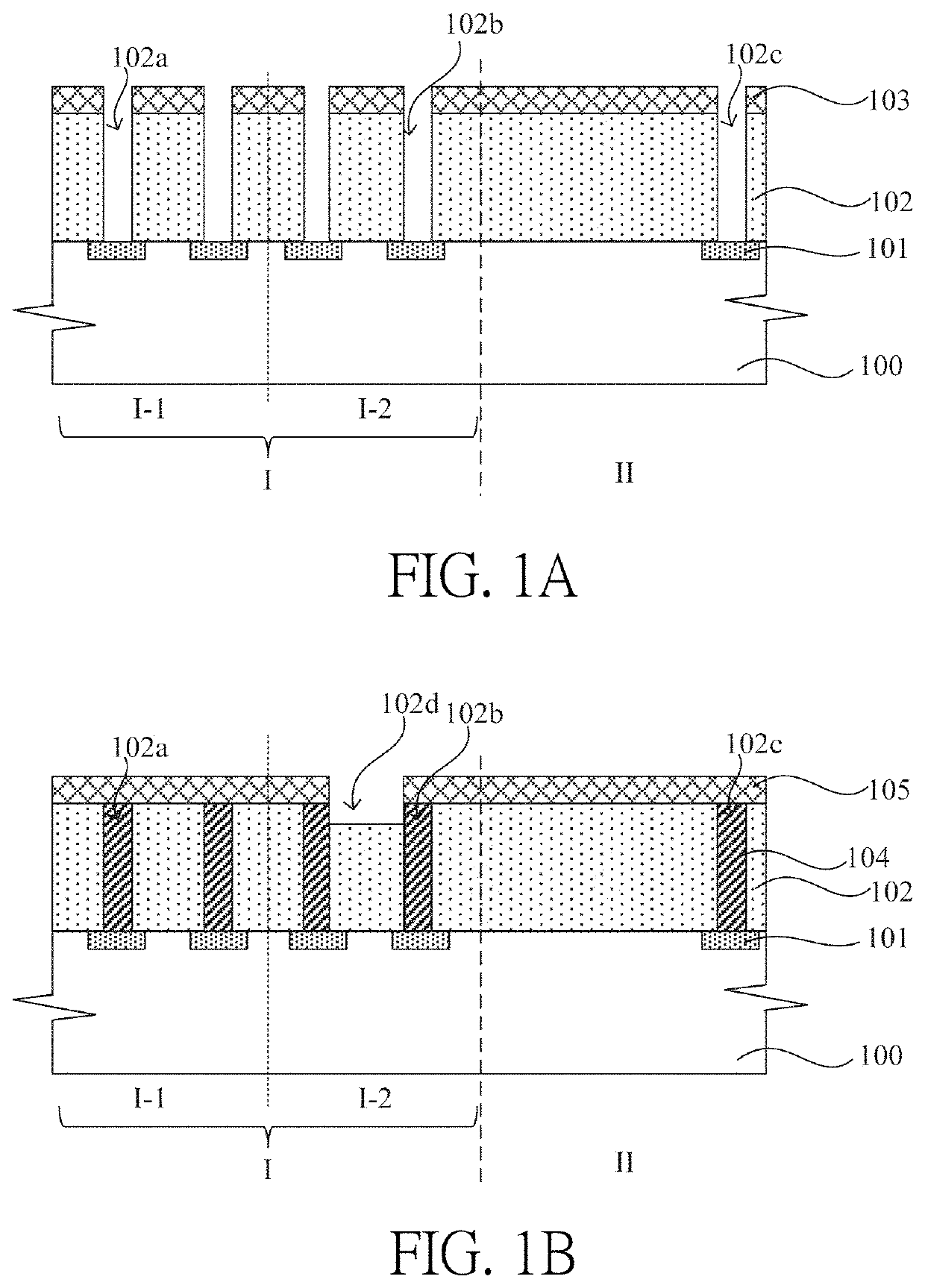
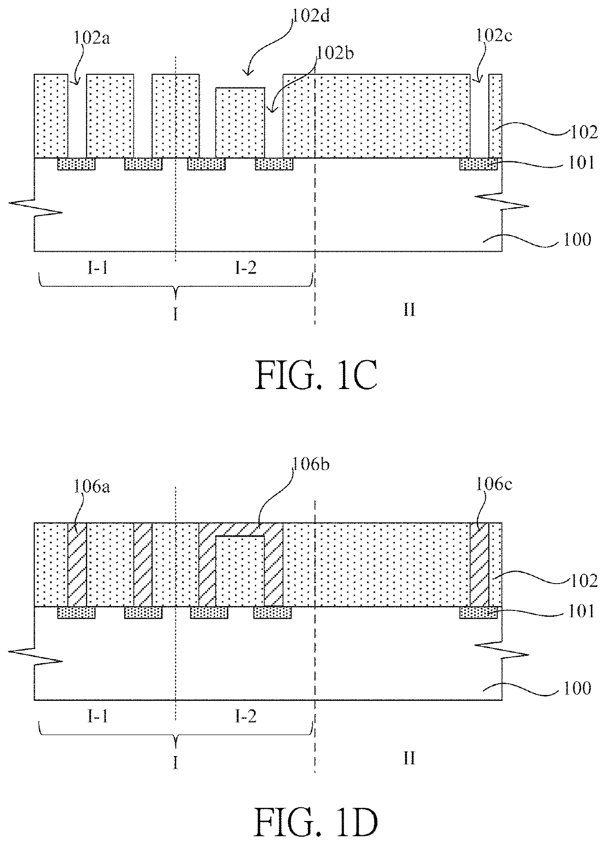
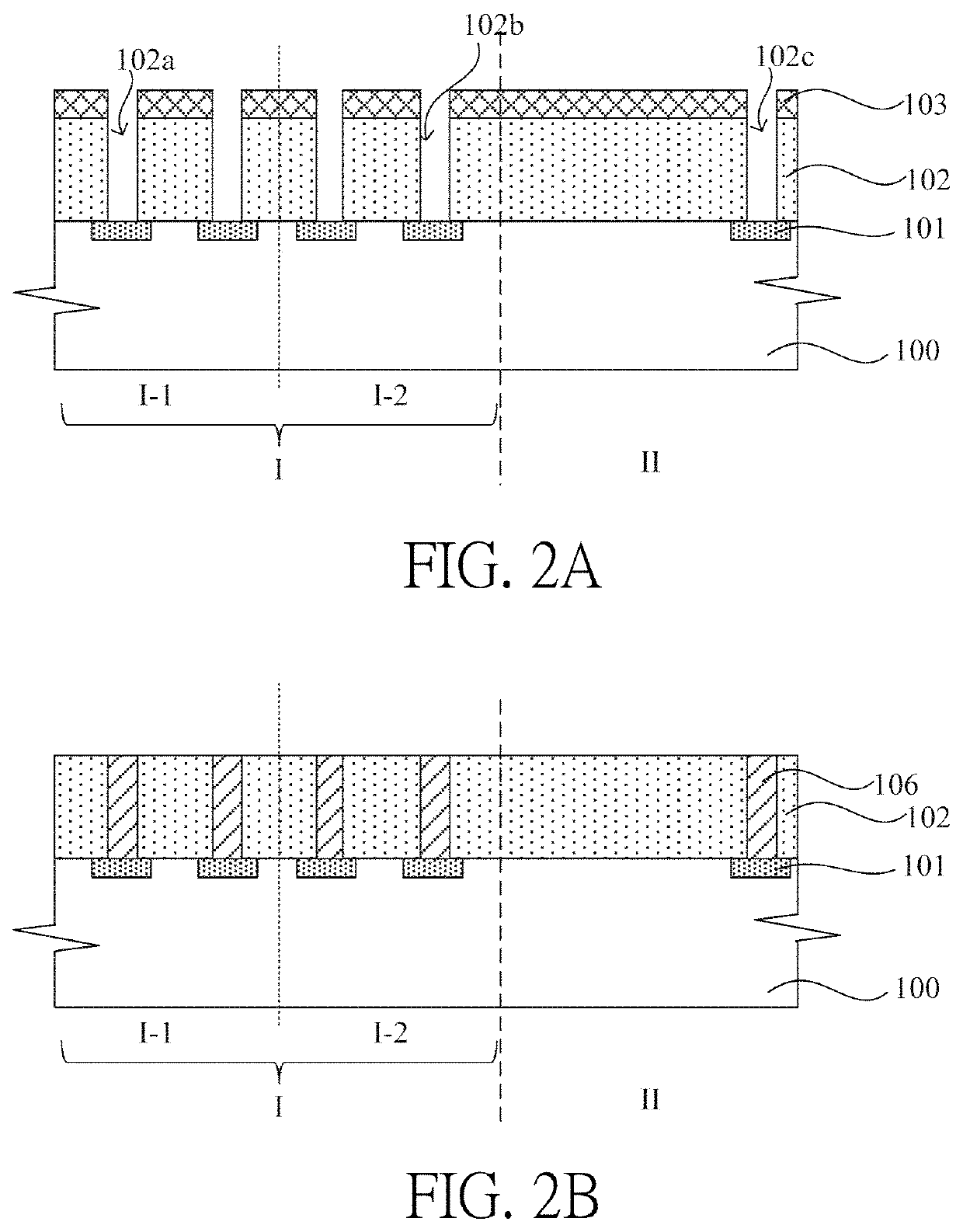
[0058]FIG. 1D is a schematic cross-section of a contact structure of semiconductor device in an embodiment of present invention. Please refer to FIG. 1D. The contact structure of semiconductor device provided in an embodiment of present invention includes multiple contact plugs 106a, 106b, wherein the contact plugs 106a, 106b are formed on core components (not shown) in a core region I of the semiconductor device, and the bottoms of contact plugs 106a, 106b contact active areas 101 of corr...


PUM


Abstract

A contact structure, contact pad layout and structure, mask combination and manufacturing method thereof is provided in the present invention. Through the connection of tops of at least two contact plugs in the boundary of core region, an integrated contact with larger cross-sectional area is formed in the boundary of core region. Accordingly, the process of forming electronic components on the contact structure in the boundary of core region may be provided with sufficient process window to increase the size of electronic components in the boundary, lower contact resistance, and the electronic component with increased size in the boundary buffer the density difference of circuit patterns between the core region and the peripheral region, thereby improving optical proximity effect and ensuring the uniformity of electronic components on the contact plugs inside the boundary of core region, and avoiding the collapse of electronic components on the contact plug in the boundary.

Description

CROSS REFERENCE TO RELATED APPLICATIONS[0001]This application is a continuation of PCT Application No. PCT / CN2020 / 079580 filed on Mar. 17, 2020, the entire contents of which are incorporated herein by reference.BACKGROUND OF THE INVENTION1. Field of the Invention[0002]The present invention relates generally to a semiconductor technology, more specifically, to a contact structure and the manufacturing method thereof, contact pad layout, contact pad, mask combination, semiconductor device and manufacturing method thereof.2. Description of the Prior Art[0003]Various technologies have been used to integrated more circuit patterns in a limited area of semiconductor substrate or chip. Since circuit patterns have different spacings, integrated circuits are generally divided into device dense regions (Dense), device loose regions (ISO) and device isolated region. Device dense region is a region with higher device density (i.e. devices are closely-spaced), device loose region is a region wit...

Claims


Application Information

Patent Timeline
Patent Type & Authority Applications(United States)
IPC IPC(8): H01L27/108H10B12/00
CPCH01L27/10855H01L27/10814H01L27/10823H01L27/10894H01L27/10876H01L27/10885H01L27/10888H01L27/10897H10B12/315H10B12/0335H10B12/09H10B12/34H10B12/50H10B12/053H10B12/482H10B12/485
Inventor TUNG, YU-CHENGJHAN, YI-WANGHUANG, YUNG-TAIFANG, XIAOPEIWU, SHAOYITSENG, YI-LEI
Owner FUJIAN JINHUA INTEGRATED CIRCUIT CO LTD
Learn More