Ion implanting method and apparatus

a technology which is applied in the field of implanting method and ion beam current, can solve the problems of inability to apply above conventional techniques, complicated control and mechanism, and inability to process substrates in a long time, so as to reduce the width of the transient region, prevent the reduction of beam current, and facilitate control

Inactive Publication Date: 2008-05-20
NISSIN ION EQUIP CO LTD
View PDF21 Cites 18 Cited by
  • Summary
  • Abstract
  • Description
  • Claims
  • Application Information

AI Technical Summary

Benefits of technology

[0045]Further, the direction of changing the scanning speed of the ion beam is one-dimension, i.e. X direction or Y direction. For this reason, by reducing the size of the ion beam in the pertinent one dimension, the width of the transient region can be decreased while reduction in the beam current is prevented.
[0046]Since the direction of changing the scanning speed of the ion beam is one-dimension as described above, and also the scanning speed is only changed, the control can be easily made. The rotation of the substrate as described above can be implemented itself by the known simple technique. Thus, the above control can be easily made and the mechanism will not be complicated.

Problems solved by technology

It is not practical to take a long time to process the substrate 2.
The above conventional technique cannot be applied as it is to this hybrid scan system.
This makes the necessary control and mechanism complicate, and leads to high cost.
Therefore, the above modification cannot be easily realized.

Method used


Image

  • Ion implanting method and apparatus
  • Ion implanting method and apparatus
  • Ion implanting method and apparatus

Examples


Embodiment Construction

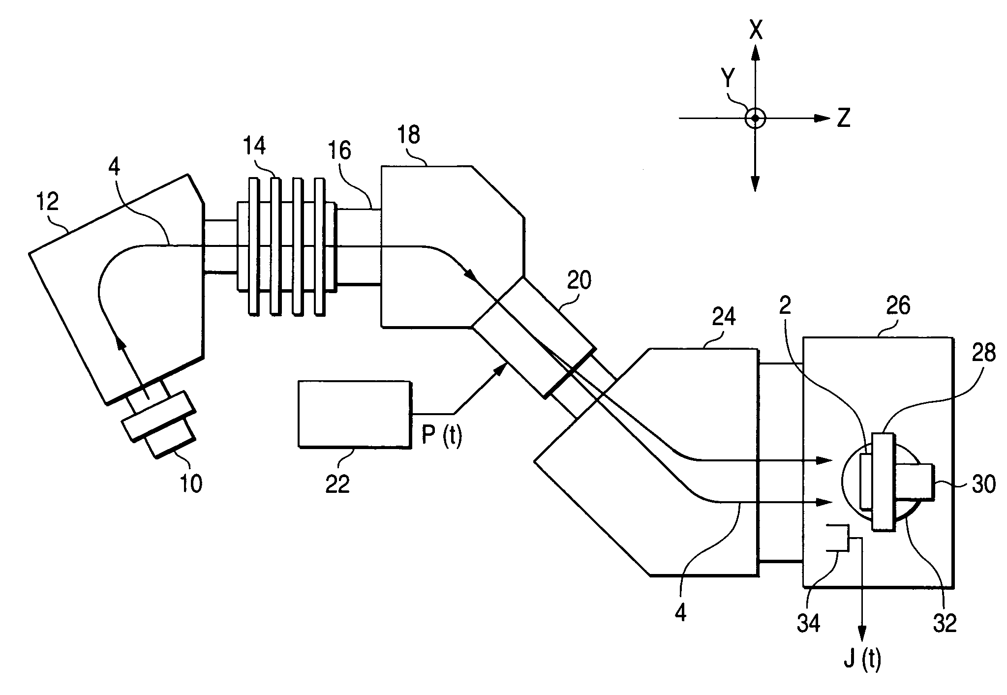
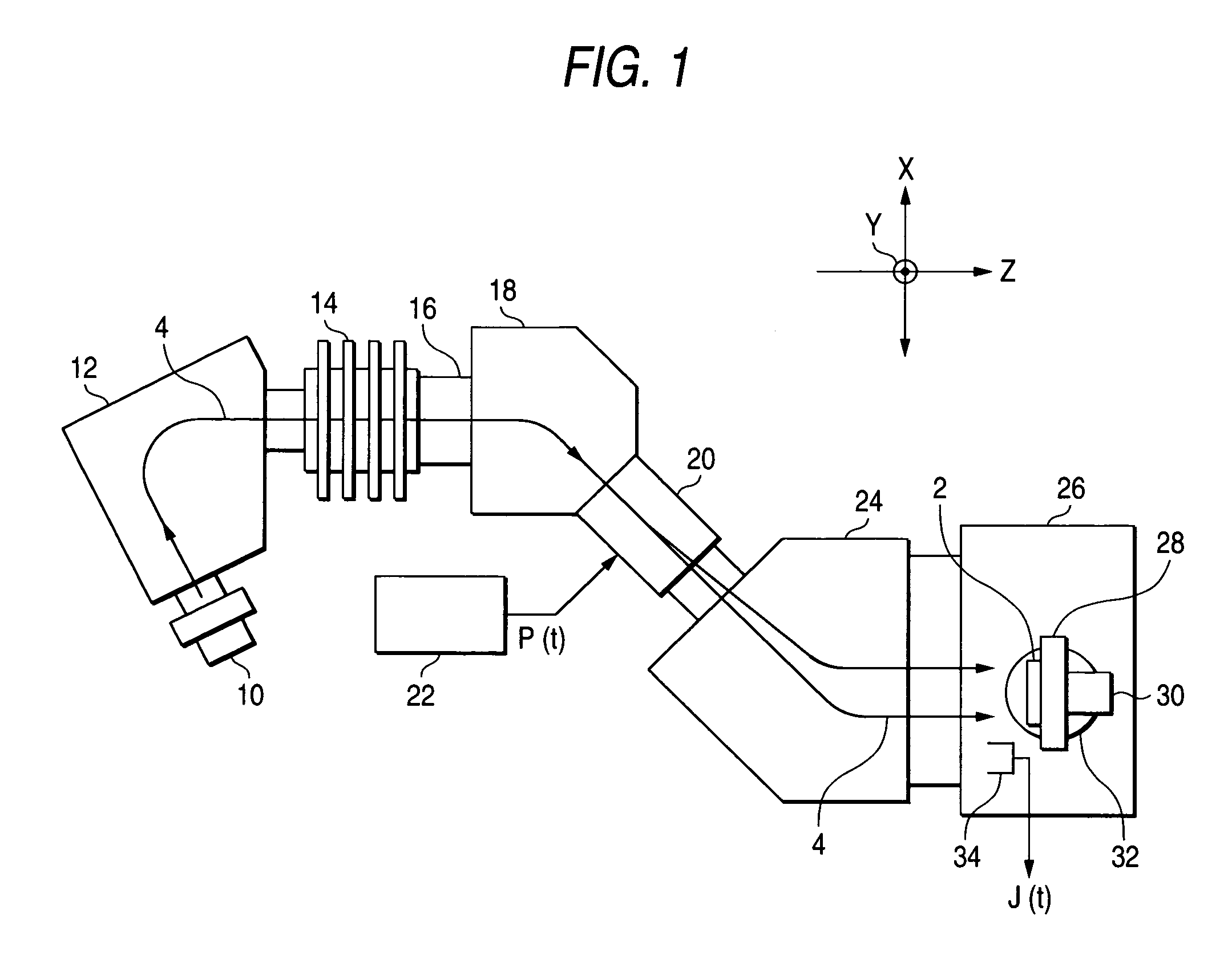
[0062]FIG. 1 is a schematic plan view showing an example of an ion implanting apparatus for implementing the ion implantation method according to this invention. FIG. 2 is an enlarged schematic side view showing an example of a mechanism in a vicinity of a substrate in the ion implanting apparatus shown in FIG. 1.

[0063]This ion implantation apparatus adopts a hybrid scan system.

[0064]In the ion implantation apparatus, an ion beam 4 is reciprocatively scanned in an X direction (e.g. horizontal direction) by an electric field or magnetic filed. A substrate (e.g. semiconductor device) is also reciprocatively mechanically driven in a Y direction (e.g. vertical direction), which is substantially orthogonal to the X direction. Thus, ions are implanted on an entire surface of the substrate 2 by co-operation.

[0065]More specifically, the ion implanting apparatus includes an ion source 10 for extracting an ion beam 4, a mass separating magnet 12 for selectively deriving a specific ion species...


PUM

PropertyMeasurementUnit
rotating angleaaaaaaaaaa
electric fieldaaaaaaaaaa
magnetic fieldaaaaaaaaaa

Abstract

The ion implanting method uses both reciprocatively scanning an ion beam in an X direction and reciprocatively mechanically driving a substrate in a Y direction orthogonal thereto. An implanting step of implanting ions separately for two implanted regions with different dose amounts of the substrate is executed plural times by changing at the center of the substrate a driving speed of the substrate. A rotating step of rotating the substrate around its center by a prescribed angle is executed once during each of the intervals between the respective implanting steps and while the ion beam is not applied to the substrate.

Description

[0001]This is a division of application Ser. No. 10 / 280,057, filed Oct. 25, 2002, now U.S. Pat. No. 6,750,462 which claims the right to priority based on Japanese Application No. 2001-328662, filed Oct. 26, 2001, and is incorporated herein by reference.BACKGROUND OF THE INVENTION[0002]1. Field of the Invention[0003]An invention relates to an ion implanting method and apparatus for forming implanted regions with different dozes on a surface of a substrate.[0004]2. Description of the Related Art[0005]In recent years, there is a demand of forming implanted regions with different dose amounts on a surface of a single substrate. This is because forming such implanted regions is efficient to reduce a number of necessary substrates and steps in e.g. adjustment of an ion implanting apparatus and manufacturing semiconductor devices with different characteristics.[0006]An example of a technique of ion-implantation to meet the above demand is described in JP-A-2000-15407.[0007]As seen from FIG...

Claims


Application Information

Patent Timeline
Patent Type & Authority Patents(United States)
IPC IPC(8): H01J37/00C23C14/48H01J37/317H01L21/265
CPCH01J37/3171H01J2237/20228H01L21/265
Inventor IWASAWA, KOJINAGAI, NOBUO
Owner NISSIN ION EQUIP CO LTD
Why Eureka
Try Eureka