Sheet feeding apparatus and image forming apparatus

a feeding apparatus and a technology of forming apparatus, applied in the direction of transportation and packaging, thin material processing, article separation, etc., can solve the problems of inability to achieve the effect of vibration suppression, inability to sufficiently reduce the vibration of the sheet itself, and uncomfortable noise, etc., to achieve the effect of suppressing the generation of unusual noise during sheet feeding

Active Publication Date: 2006-02-02
CANON KK
View PDF13 Cites 11 Cited by
  • Summary
  • Abstract
  • Description
  • Claims
  • Application Information

AI Technical Summary

Benefits of technology

[0009] The present invention has been made in view of the above-described problems, and has as an object to provide a sheet feeding apparatus in which generation of an unusual noise during sheet feeding can be suppressed without deteriorating sheet feeding performance and to provide an image forming apparatus equipped with the same.
[0010] To achieve the above object, an apparatus according to the present invention comprises a feed roller having a cut-away portion on its outer circumference, the outer circumference of the feed roller being to be in frictional contact with a top surface of a sheet stack to apply a feeding force on a sheet, a pad member that is in pressure contact with said feed roller for separating sheets between itself and the feed roller, and a roller portion having a shape smaller than the outer diameter of said feed roller and protruding outwardly beyond said cut-away portion, said roller portion coming in contact with said pad member when said cut-away portion of the feed roller is opposed to said pad member, wherein a vibration suppression member provided on a side surface of said roller portion for suppressing vibration that may occur during sheet feeding.
[0011] Another apparatus according to the present invention comprises a feed roller having a cut-away portion on its outer circumference, the outer circumference of the feed roller being to be in frictional contact with a top surface of a sheet stack to apply a feeding force on a sheet, a pad member that is in pressure contact with said feed roller for separating sheets between itself and the feed roller, and a roller portion having a shape smaller than the outer diameter of said feed roller and protruding outwardly beyond said cut-away portion, said roller portion coming in contact with said pad member when said cut-away portion of the feed roller is opposed to said pad member, wherein a pressure contact member provided in pressure contact with the outer circumferential surface of said roller portion for suppressing vibration that may occur during sheet feeding.

Problems solved by technology

In recent years, in the field of sheet feeding apparatuses equipped in image forming apparatuses such as copying machines and printers, reduction of operation noise as well as stabilization of sheet feeding performance has been a challenge that has been receiving attention.
In this sheet separating method, stick-slip (minor vibration) may occur between the sheet and the separating pad depending on the type of the sheet fed, and this vibration sometimes causes an unusual noise (uncomfortable noise).
However, although vibration of the separating pad can be effectively reduced by the above-described conventional method, it is not possible to sufficiently reduce vibration of the sheet itself, which is the source origin of the vibration.
Accordingly, there is a possibility that the vibration suppression effect cannot be achieved depending on the structure of the sheet feeding apparatus and that the vibration may be magnified to make the unusual noise lauder.
However, when the contact pressure is made small, sufficient sheet feeding performance cannot be achieved, and sheet feed failure may occur.
In contrast, when the contact pressure is made large, the possibility of occurrence of stick-slip between the sheet and the separating pad increases to make the possibility of generating an unusual noise higher.

Method used


Image

  • Sheet feeding apparatus and image forming apparatus
  • Sheet feeding apparatus and image forming apparatus
  • Sheet feeding apparatus and image forming apparatus

Examples


first embodiment

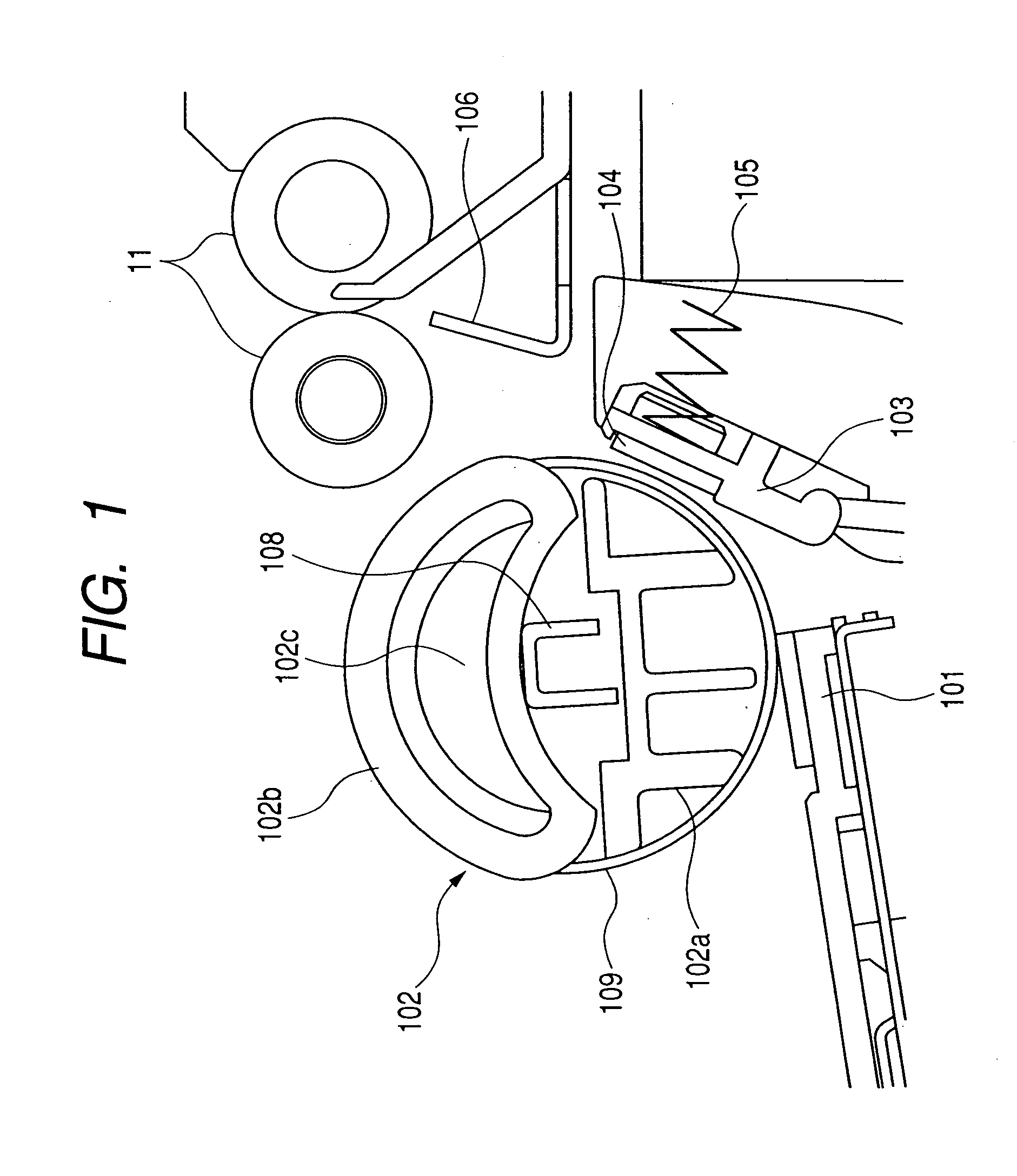
[0023] A sheet feeding apparatus according to the first embodiment and an image forming apparatus equipped with the same will be described with reference to FIGS. 1 to 6.

(Overall Structure of the Image Forming Apparatus)

[0024] Firstly, the overall structure of the image forming apparatus equipped with the sheet feeding apparatus will be briefly described with reference to FIG. 6.

[0025] As shown in FIG. 6, a sheet feeding apparatus A is provided in the lower portion of the main body of the image forming apparatus. The structure of the sheet feeding apparatus A will be described in detail later. A sheet S fed from the sheet feeding apparatus A is conveyed to an image forming portion by means of a conveying roller pair 11 and a registration roller pair 12. The image forming portion in this embodiment is adapted to form an image using an electrophotography process and provided with an electrophotographic photosensitive drum 13 and charging means (not shown) and developing means (not...

second embodiment

[0048] Next, a sheet feeding apparatus according to the second embodiment will be described with reference to FIGS. 7A and 7B. The basic structure of the apparatus according to this embodiment is the same as that of the above-described first embodiment, and redundant descriptions thereof will be omitted. Here, features that characterize this embodiment will be described. Members having the functions same as those in the above-described first embodiment will be designated by the same reference signs.

[0049] This embodiment differs from the above-described first embodiment in that the damping members 201 are not provided on the roller portions, but pressure contact members for externally biasing the roller portions 109 are provided.

[0050]FIGS. 7A and 7B schematically show the structure of examples of the pressure contact member in the sheet feeding apparatus according to the second embodiment. FIG. 7A shows a pressure contact member 501 having elasticity opposed to the roller portion...

third embodiment

[0055] Next, an apparatus according to the third embodiment will be described with reference to FIGS. 8 and 9. The basic structure of the apparatus according to this embodiment is the same as that of the above-described first embodiment, and redundant descriptions thereof will be omitted. Here, features that characterize this embodiment will be described. Members having the functions same as those in the above-described first embodiment will be designated by the same reference signs.

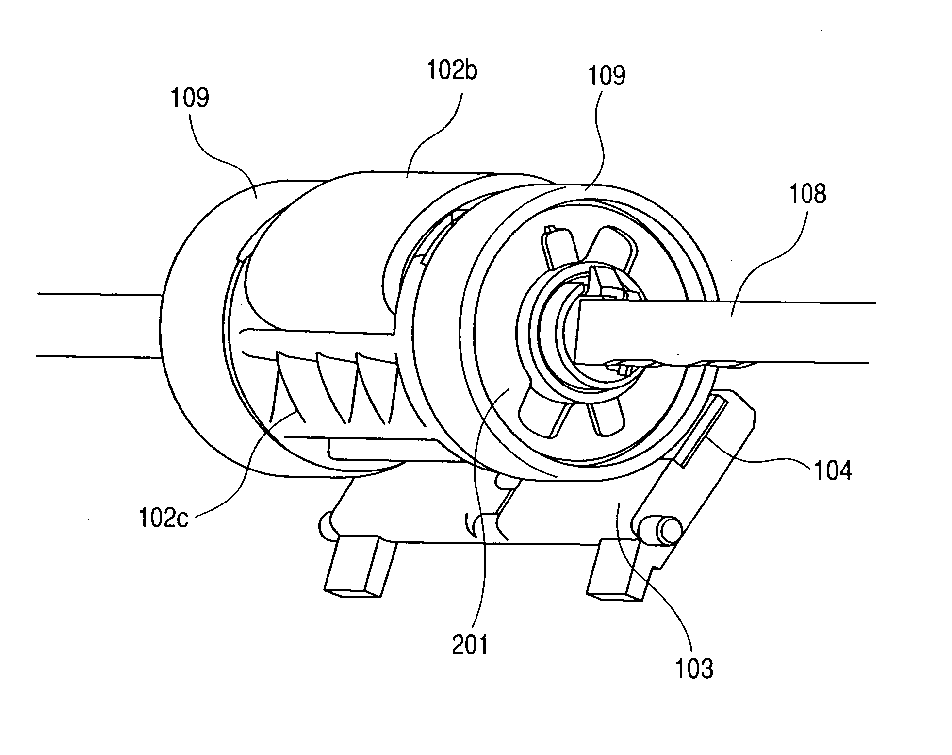
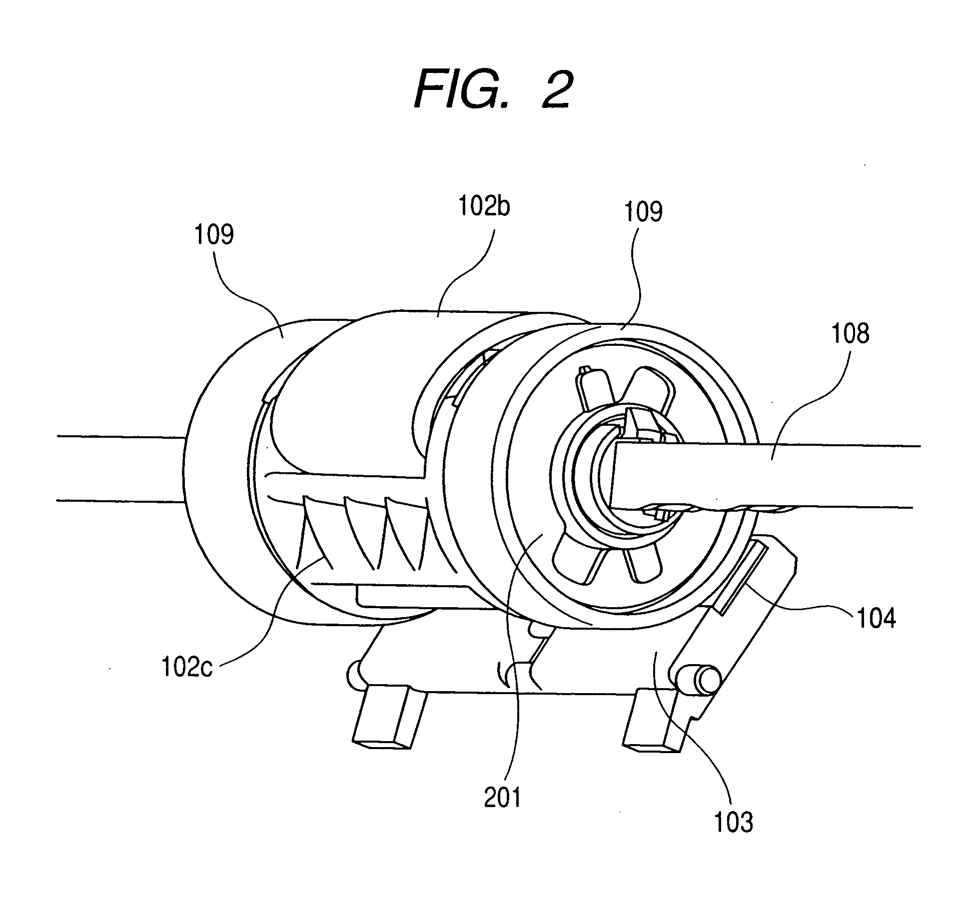
[0056] This invention differs from the above-described embodiment in that the total weight of the roller portions 109 is determined in such a way as to suppress vibration of the sheet.

[0057] In this embodiment, damping members 201 in the form of metal pieces are attached to adjust the total weight of the roller portions 109. The roller portion 109 is made of a POM material, and a metal piece 201 having a thickness of 1 mm is attached thereto. Thus, the total weight of each roller portion 109 and dampin...


PUM


Abstract

An apparatus is provided with a feed roller that is rotatable to apply a feeding force on a sheet, a separating pad for pressing the sheet against the feed roller and a roller portion provided coaxially with a support shaft of the feed roller to position the feed roller relative to the separating pad. A damping member for suppressing vibration of the sheet is provided on a side surface of the roller portion to prevent an unusual noise from being generated.

Description

BACKGROUND OF THE INVENTION [0001] 1. Field of the Invention [0002] The present invention relates to a sheet feeding apparatus for feeding a copying machine, a facsimile machine, a printer or the like with originals or recording sheets and relates to an image forming apparatus using the same. [0003] 2. Description of Related Art [0004] In recent years, in the field of sheet feeding apparatuses equipped in image forming apparatuses such as copying machines and printers, reduction of operation noise as well as stabilization of sheet feeding performance has been a challenge that has been receiving attention. [0005] The sheet feeding apparatus used in a copying machine, a printer or the like is adapted to separate and send out stacked sheets one after another. In a conventional method adopted in the sheet feeding apparatus, sheets are separated one by one by means of a feed roller for feeding a sheet and a separating pad that is biased against the feed roller to prevent double feeding. ...

Claims


Application Information

Patent Timeline
Patent Type & Authority Applications(United States)
IPC IPC(8): B65H3/52
CPCB65H3/5223B65H1/04
Inventor MURAMATSU, MOTOYASU
Owner CANON KK
Why Eureka
Try Eureka