Rotor disk for a turbomachine

a technology of rotating disks and turbomachines, which is applied in the direction of liquid fuel engines, vessel construction, marine propulsion, etc., can solve the problems of high centrifugal force on the blade, difficult or impossible deformation by compression, and loosening or jamming of the locking member screws, etc., to achieve the effect of simple, effective and inexpensiv

Active Publication Date: 2006-02-02
SN DETUDE & DE CONSTR DE MOTEURS DAVIATION S N E C M A
View PDF8 Cites 3 Cited by
  • Summary
  • Abstract
  • Description
  • Claims
  • Application Information

AI Technical Summary

Benefits of technology

[0009] A particular object of the invention is to provide a solution to the problem that is simple, inexpensive, and effective.

Problems solved by technology

When the turbomachine is in operation, the blades are subjected to high levels of centrifugal force and to vibration that can lead to the screws of the locking member loosening or jamming.
Nevertheless, such deformation by compression is difficult or impossible to achieve when the pitch between the blades is small and hinders or prevents a compression tool being put into place.
It has also been found that such jamming of the screws makes it impossible to disassemble the locking members, thereby making it necessary to destroy them with a drill, and that runs the risk of damaging the rotor disk.
It is not always easy to get hold of the ends of these parts and to clamp them together by means of the tool so as to enable the parts to be slid along the groove into their locking zones, and as a general rule, it is even more difficult to move them in the opposite direction for the purpose of unlocking the blade roots and disassembling the blades.

Method used


Image

  • Rotor disk for a turbomachine
  • Rotor disk for a turbomachine
  • Rotor disk for a turbomachine

Examples


Embodiment Construction

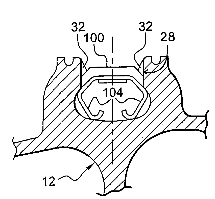
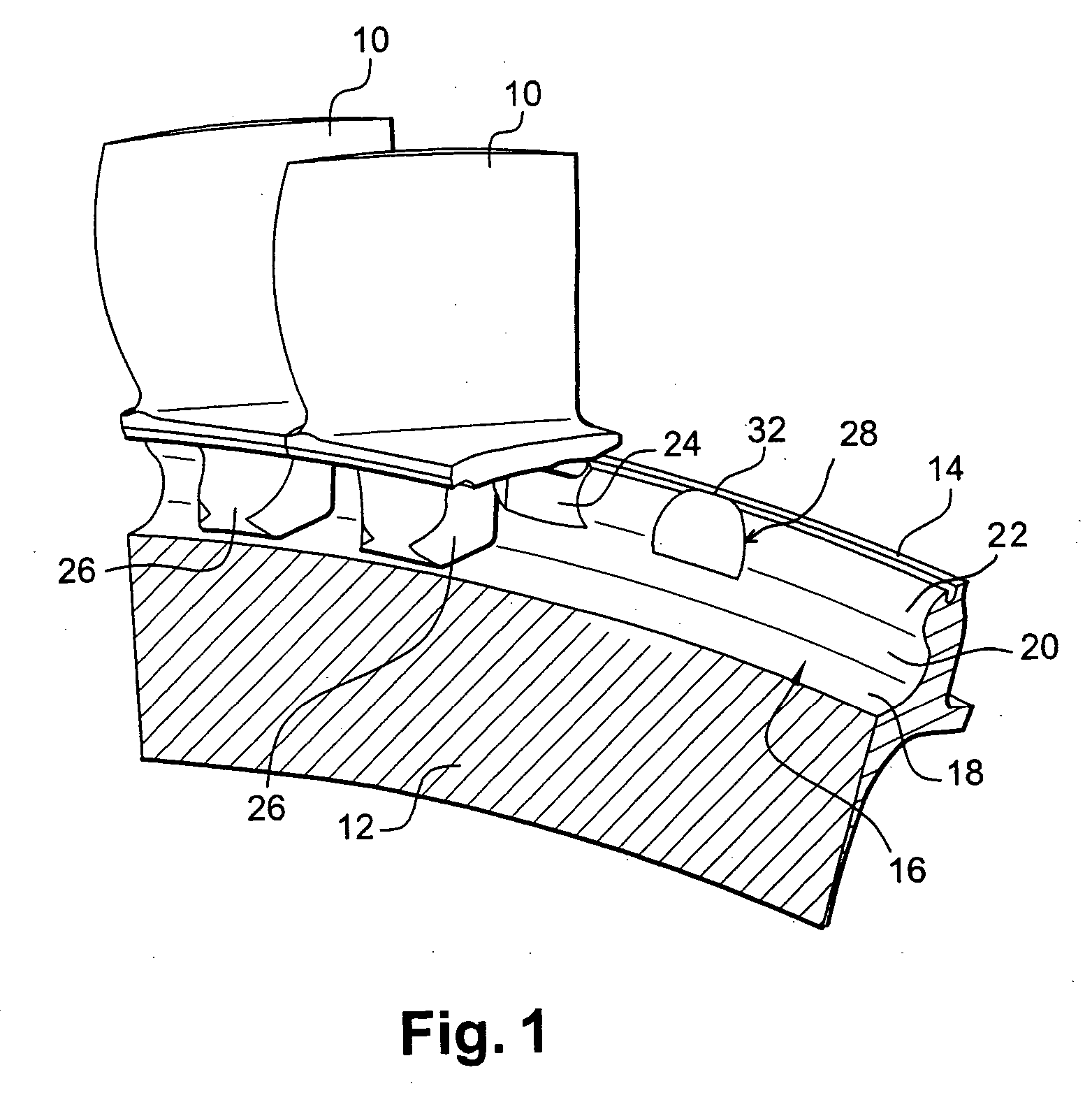
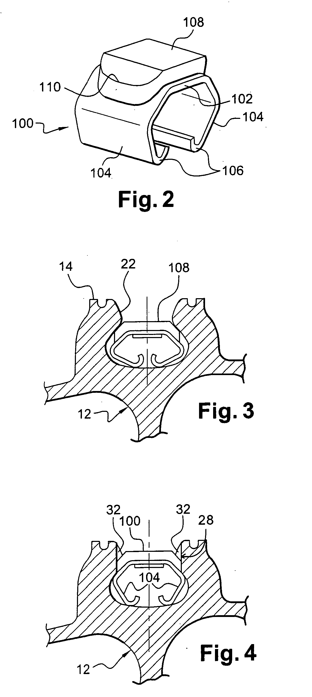
[0024]FIG. 1 shows a disk 12 of a turbomachine rotor, in particular of a high pressure or low pressure compressor of a turbojet, the disk 12 having at its outer periphery a cylindrical surface 14 in which there is formed a groove 16 that is open radially outwards.

[0025] In conventional manner, this groove 16 has a cross-section that is dovetail-shaped, Christmastree-shaped, or the like. The groove 16 in the disk 12 in the example shown has an annular bottom wall 18 that is substantially flat and two side walls 20 each carrying an axially-directed rim 22 on its radially outer portion extending towards the opposite side wall 20, with the opening of the groove 16 being narrower than its bottom 18.

[0026] The groove includes a window 24 for inserting the roots 26 of the blades 10 of the disk 12, which roots are complementary in shape to the groove 16.

[0027] The window 24 is formed by cutting through the above-mentioned rims 22 of the side walls 20 of the groove 16 over a length of cir...


PUM


Abstract

A rotor disk for a turbomachine, the disk carrying blades whose roots are retained in a peripheral groove of the disk, said groove including a window for inserting blade roots and a locking member that is a single elastically deformable piece and dimensioned to be received and retained in a notch of the groove while in its free state, and to be capable of being displaced to slide inside the groove while in a stressed and elastically deformed state.

Description

[0001] The present invention relates to a rotor disk for a turbomachine, the disk being of the type comprising an outer cylindrical surface formed with a peripheral groove in which the roots of the blades of the disk are retained. BACKGROUND OF THE INVENTION [0002] The blade roots are inserted into the disk groove via a window formed in said groove, and they are held radially and axially relative to the axis of the turbomachine by having co-operating shapes, the groove having a cross-section that is of dovetail-shape, or the like, for example. [0003] In order to prevent the blade roots from sliding freely in the groove of the disk and escaping therefrom through the above-mentioned window, a locking member is inserted through said window into the groove in the disk for the purpose of being displaced within the groove by sliding until it reaches a retaining notch formed in the groove. [0004] Document FR-A-2 810 366 discloses locking members each comprising a radial screw with a head d...

Claims


Application Information

Patent Timeline
Patent Type & Authority Applications(United States)
IPC IPC(8): B63H1/20F01D5/30
CPCF01D5/3038F05D2300/501F05D2260/30
Inventor CHATEL, ALAIN JEAN CHARLESDEZOUCHE, LAURENT GILLESJOLY, PHILIPPE
Owner SN DETUDE & DE CONSTR DE MOTEURS DAVIATION S N E C M A
Why Eureka
Try Eureka