Oil and fuel circuits in a turbine engine

a technology of oil and fuel circuits, which is applied in the direction of turbine/propulsion fuel heating, machines/engines, mechanical equipment, etc., can solve the problems of insufficient heat exchange capacity of the main heat exchanger for transferring heat from the oil flow to the fuel flow, and disturb the operation of the servo-valves controlling the variable geometry members, etc., to achieve the effect of simple, effective and inexpensiv

Active Publication Date: 2017-08-22
SN DETUDE & DE CONSTR DE MOTEURS DAVIATION S N E C M A
View PDF15 Cites 4 Cited by
  • Summary
  • Abstract
  • Description
  • Claims
  • Application Information

AI Technical Summary

Benefits of technology

The invention aims to solve problems in a simple and cost-effective way. It aims to avoid the drawbacks of previous solutions by providing an effective solution.

Problems solved by technology

That type of configuration for the oil and fuel circuits is nevertheless not entirely satisfactory.
Under cold operating conditions, the capacity of the main heat exchanger for transferring heat from the oil flow to the fuel flow can be insufficient.
In a cold environment, water present in the fuel circuit can freeze, thereby disturbing the feeding of fuel to the injectors in the combustion chamber and greatly disturbing the operation of the servo-valves controlling variable geometry members.
Nevertheless, under hot operating conditions, the secondary oil / fuel heat exchanger contributes significant heating to the fuel fed to the servo-valves, thereby increasing the risk of the fuel overheating and thus of the fuel coking.
Introducing a secondary oil / fuel heat exchanger in series with the main oil / fuel heat exchanger and the oil / air heat exchanger gives rise to an increase in head losses in the oil circuit.

Method used


Image

  • Oil and fuel circuits in a turbine engine
  • Oil and fuel circuits in a turbine engine
  • Oil and fuel circuits in a turbine engine

Examples


Embodiment Construction

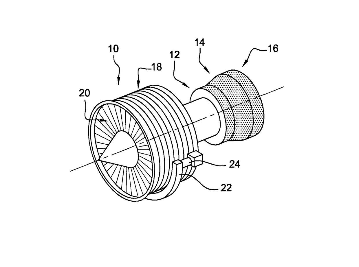
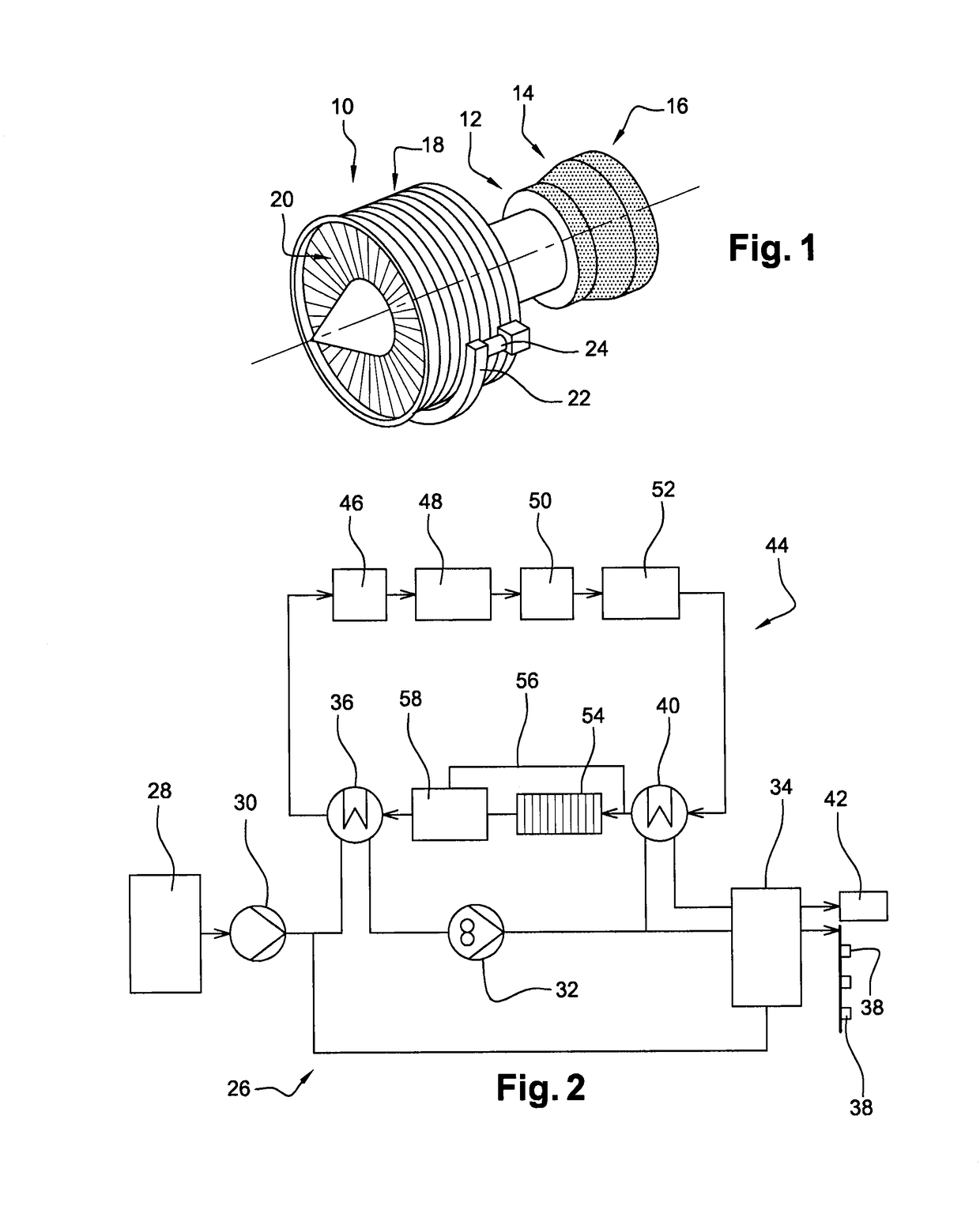
[0033]In well-known manner to the person skilled in the art, a turbine engine 10 comprises a combustion chamber 12, with combustion gas from the chamber 12 driving a high pressure turbine 14 and a low pressure turbine 16. The high pressure turbine 14 is coupled by a shaft to a high pressure compressor 18 arranged upstream from the combustion chamber 12 and feeding it with air under pressure. The low pressure turbine 16 is coupled by another shaft to a fan 20 arranged at the upstream end of the engine 10.

[0034]An accessory gearbox 22 is connected via a mechanical takeoff 24 to the shaft of the high pressure turbine and contains gearing for driving various pieces of equipment of the engine, such as pumps and generators, in particular electricity generators.

[0035]FIG. 2 shows the oil and fuel circuits of the FIG. 1 engine.

[0036]The fuel circuit 26 comprises, from upstream to downstream in the flow direction of the fuel: a fuel tank 28; a low pressure pump 30; a high pressure pump 32; a...


PUM


Abstract

Oil and fuel circuits in a turbine engine, the circuits including a main oil / fuel heat exchanger passing flows of oil and fuel for cooling the oil, an oil / air heat exchanger mounted in the oil circuit and having a flow of cooling air passing therethrough, a bypass pipe connected between an oil inlet and outlet of the oil / air heat exchanger, a valve for controlling passage of the oil flow through the bypass pipe and the oil / air heat exchanger, and a secondary oil / fuel heat exchanger mounted in the bypass pipe.

Description

BACKGROUND OF THE INVENTION[0001]Field of the Invention[0002]The invention relates to oil and fuel circuits in a turbine engine such as an airplane turbojet or turboprop.[0003]Description of the Related Art[0004]It is known to connect the oil and fuel circuits via heat exchangers in order to avoid the oil for lubricating members such as rolling bearings from overheating, the oil being cooled by exchanging heat with the flow of fuel that is fed to injectors mounted in a combustion chamber and to servo-valves for controlling variable geometry members such as variable pitch vanes.[0005]To this end, a main oil / fuel heat exchanger is used that is arranged in the oil and fuel circuits downstream or upstream relative to an oil / air heat exchanger mounted in the oil circuit for cooling the oil leaving the core of the turbine engine. The oil / air heat exchanger has a stream of air passing therethrough or thereover that comes from outside the turbine engine.[0006]A bypass pipe is mounted on thi...

Claims


Application Information

Patent Timeline
Patent Type & Authority Patents(United States)
IPC IPC(8): F02C7/14F02C7/12F01D25/18F02C7/224
CPCF02C7/12F01D25/18F02C7/14F02C7/224F05D2260/20F05D2260/213Y02T50/676Y02T50/60
Inventor GAMEIRO, SEBASTIENDELEPIERRE-MASSUE, OLIVIER ROBERT MICHEL
Owner SN DETUDE & DE CONSTR DE MOTEURS DAVIATION S N E C M A
Why Eureka
Try Eureka