Welding tool

a welding tool and tool body technology, applied in the field of welding tools, to achieve the effect of improving the quality of welding, being convenient to use, and being convenient to us

Active Publication Date: 2008-07-15
SN DETUDE & DE CONSTR DE MOTEURS DAVIATION S N E C M A
View PDF7 Cites 4 Cited by
  • Summary
  • Abstract
  • Description
  • Claims
  • Application Information

AI Technical Summary

Benefits of technology

[0007]A particular object of the invention is to provide a solution to those problems that is simple, inexpensive, and effective, and to improve the quality of welding, in particular when the welding is automated.

Problems solved by technology

Such caps are fragile and need to be replaced often, their shapes are not very accurate and poorly adapted to the workpieces, and different from one cap to another, and they are relatively time-consuming to make.

Method used


Image

  • Welding tool
  • Welding tool
  • Welding tool

Examples


Embodiment Construction

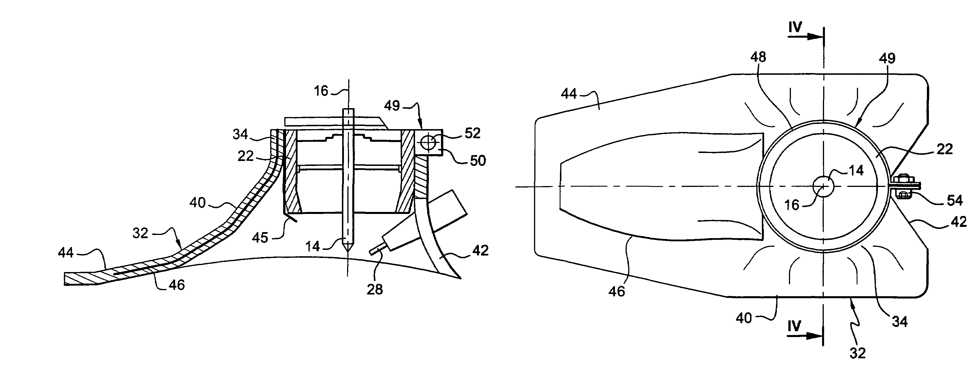
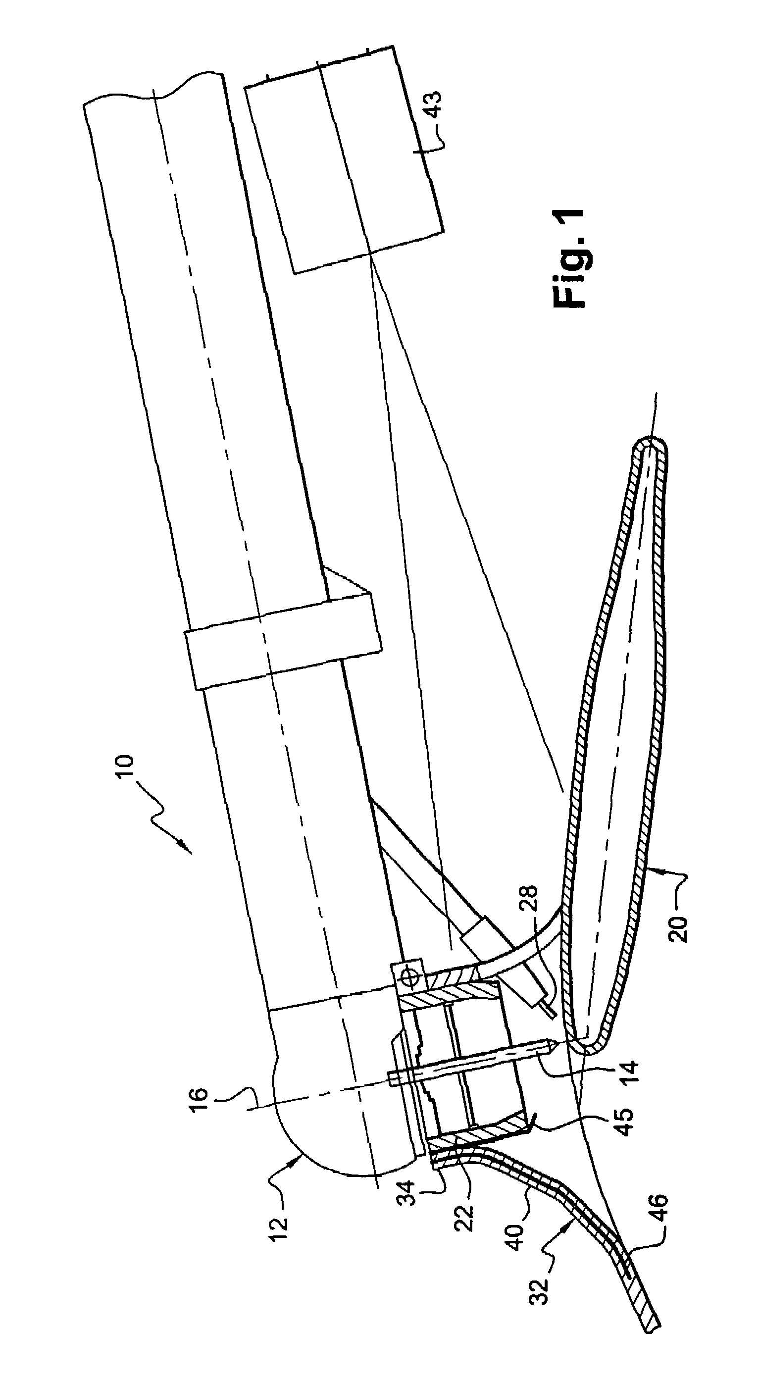
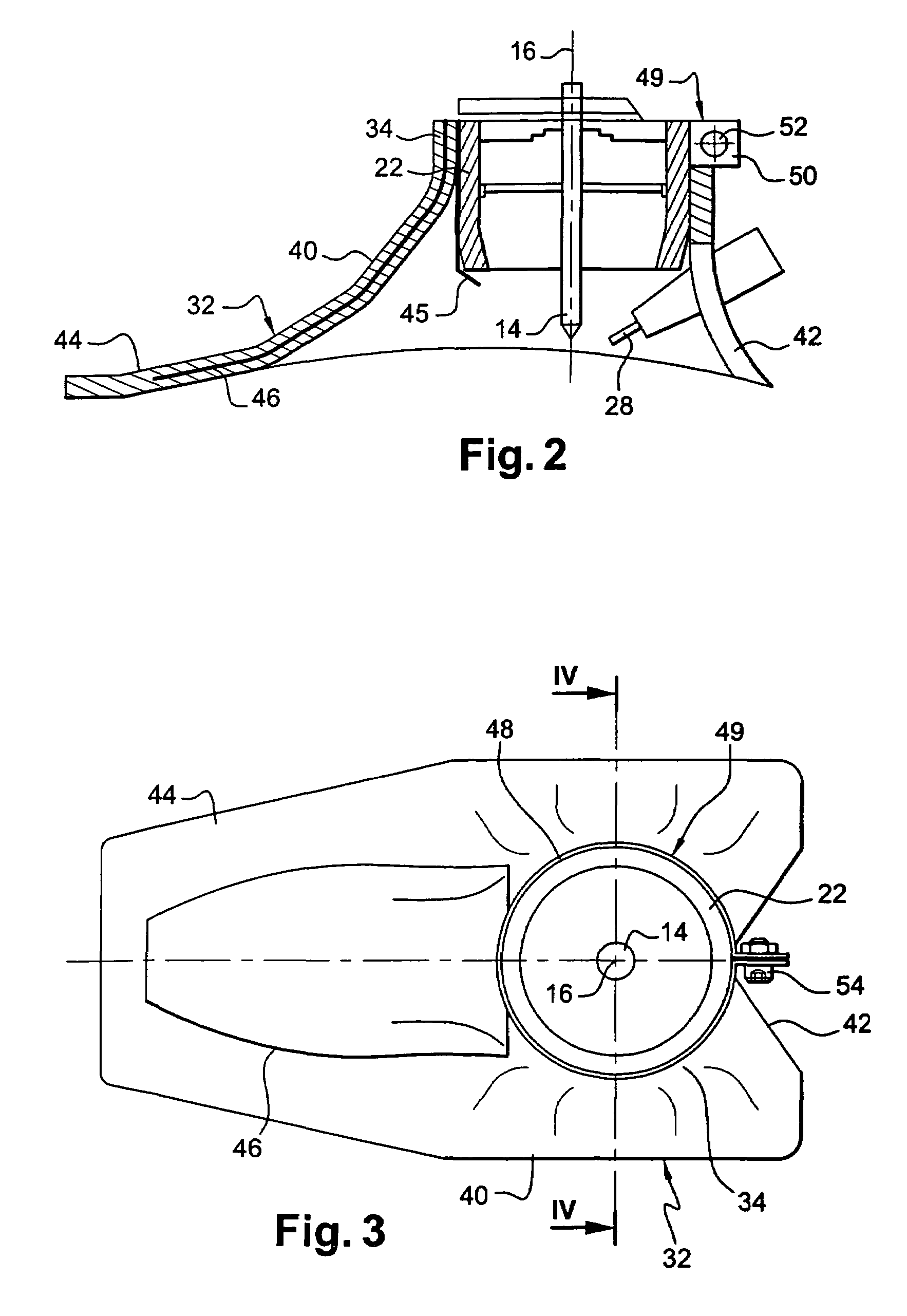
[0029]FIG. 1 is a diagram showing the front portion of a TIG arc welding tool 10 or a plasma welding tool, of the type suitable for handling by means of a robot arm.

[0030]The front portion of the tool comprises a welding head 12 carrying a refractory electrode 14, such as a rod of non-meltable tungsten, of axis 16 that is substantially perpendicular to the weld bead to be made.

[0031]During a welding operation, an electric arc is generated between the refractory electrode 14 and the junction zone between workpieces 20 that are to be assembled together so as to form a metal bath in which the materials of the workpieces 20 melt and mix together so as to constitute a weld bead after cooling down.

[0032]The top portion of the electrode 14 is surrounded by a cylindrical nozzle 22 that is shorter than the electrode 14 such that the bottom end of the electrode projects axially from the nozzle 22.

[0033]The welding operation can be performed with or without filler metal. In the implementation ...


PUM

PropertyMeasurementUnit
temperaturesaaaaaaaaaa
thickaaaaaaaaaa
temperaturesaaaaaaaaaa

Abstract

A welding tool for TIG arc welding, plasma welding or laser welding, including a welding head carrying a refractory electrode and surrounded by a skirt. The skirt is releasably fastened on the welding head and has a front portion which extends forwards and is shaped to surround a weld head with clearance over a predetermined length. The skirt is made by molding or thermoforming a composite material made of at least two layers of ceramic fibers which are bonded together by an elastomer that withstands high temperatures.

Description

[0001]The present invention relates to a welding tool, in particular for tungsten inert gas (TIG) arc welding or plasma welding or laser welding.BACKGROUND OF THE INVENTION[0002]A TIG arc welding tool or a plasma welding tool comprises a head carrying a refractory electrode, such as a rod of non-meltable tungsten, capable of generating an electric arc in association with workpieces to be assembled together so as to form a weld bead between them by melting and mixing their materials.[0003]A laser welding tool comprises a laser generator capable of generating a high energy beam that is applied to the workpieces to form a weld bead between them by melting and mixing their materials.[0004]Such welding tools include means for feeding an inert gas to the head of the tool, the inert gas being for projecting onto the weld bead formed by the molten materials so as to protect said materials against oxidation by the ambient atmosphere.[0005]In order to improve the protection, welders are in th...

Claims


Application Information

Patent Timeline
Patent Type & Authority Patents(United States)
IPC IPC(8): B23K9/167B23K9/16B23K26/14
CPCB23K9/16B23K26/032B23K26/1476B23K26/147B23K26/1405B23K26/142B23K9/167B23K9/296B23K9/32B23K10/02B23K26/12
Inventor CAUSTE, ERIC YVES ROGERFLESCH, THIERRY JEAN EMILE
Owner SN DETUDE & DE CONSTR DE MOTEURS DAVIATION S N E C M A
Why Eureka
Try Eureka