Axisymmetric part for an aviation turbine engine rotor

a technology of aviation turbine engine and rotor, which is applied in the direction of machines/engines, liquid fuel engines, combustion air/fuel air treatment, etc., can solve the problems of penalizing the cost of fabrication, and existing composite connections that do not incorporate the function of radially retaining adjacent parts, etc., to achieve the desired mechanical strength and aerodynamic performance constraints, simple, effective, and cost-effective

Active Publication Date: 2016-03-15
SAFRAN +1
View PDF14 Cites 4 Cited by
  • Summary
  • Abstract
  • Description
  • Claims
  • Application Information

AI Technical Summary

Benefits of technology

[0007]An object of the present invention is thus to propose a link part in a turbine engine that satisfies the desired mechanical strength and aerodynamic performance constraints. The invention also seeks to provide a solution to this problem that is simple, inexpensive, and effective.
[0009]It is thus possible to guarantee the radial retention function of the platform while also achieving a maximum weight saving as a result of using a composite material for the most part.

Problems solved by technology

The connection with the fan platform is subjected both to mechanical strength constraints and to aerodynamic performance constraints.
The present metal-based technologies penalize the weight of the low pressure rotor line, while incorporating an aerodynamic contouring (3D flow section) function also penalizes the cost of fabrication.
Furthermore, existing composite connections do not incorporate the function of radially retaining adjacent parts.
Selecting a structure that is appropriate for this link part thus depends on a compromise between those two relatively contradictory constraints, and prior art structures do not provide a genuinely satisfactory solution to those two constraints.

Method used


Image

  • Axisymmetric part for an aviation turbine engine rotor
  • Axisymmetric part for an aviation turbine engine rotor
  • Axisymmetric part for an aviation turbine engine rotor

Examples


Embodiment Construction

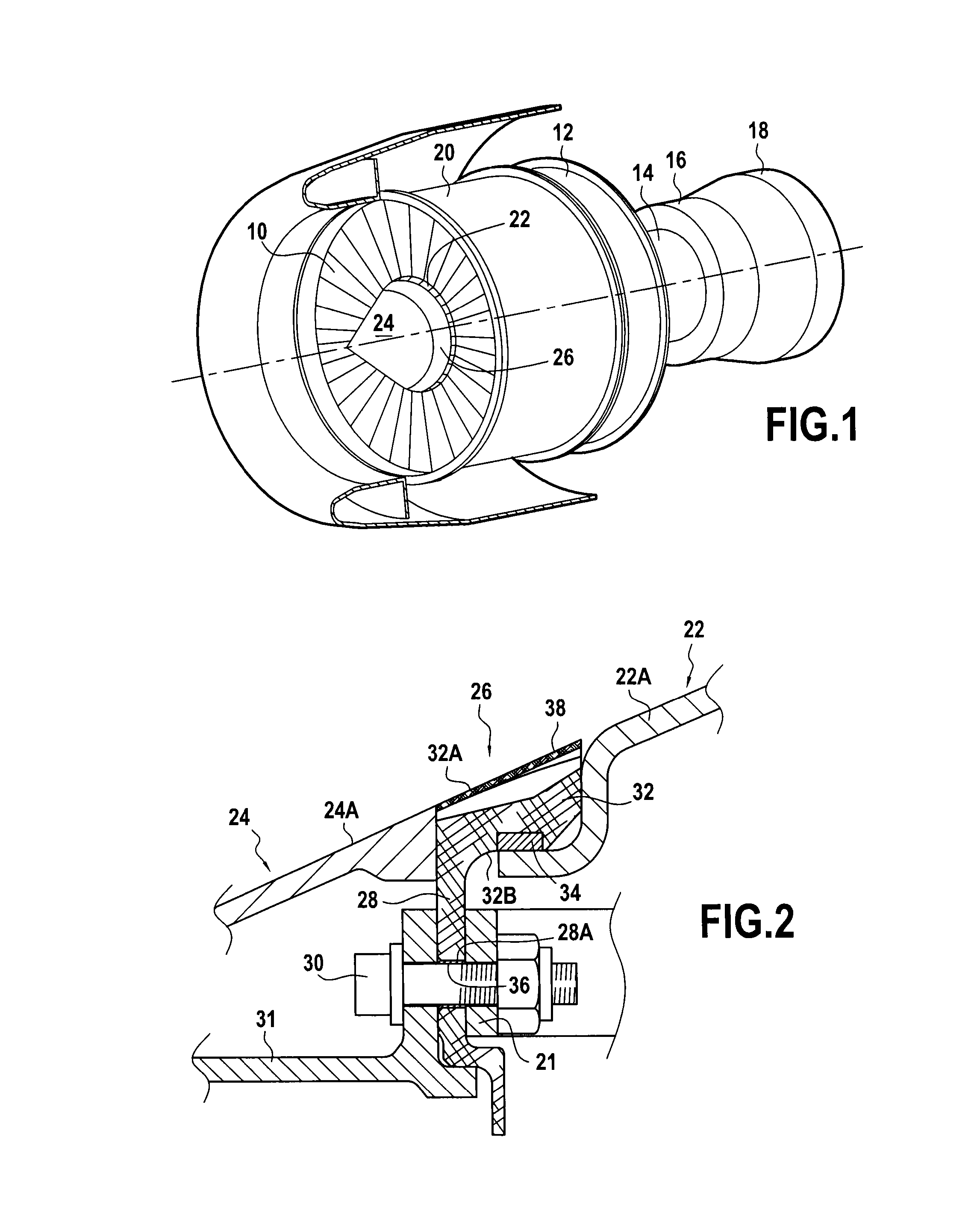
[0017]The turbojet shown diagrammatically in FIG. 1 comprises, from upstream to downstream in the flow direction of the gas stream: a fan 10 located at the inlet of the turbojet, a compressor 12, a combustion chamber 14, a high pressure (HP) turbine 16, and a low pressure (LP) turbine 18. The HP and LP turbines are coupled respectively to the compressor 12 and to the fan 10 by coaxial HP and LP shafts (not shown).

[0018]The turbojet is housed in a casing made up of a plurality of portions, each corresponding to one of those various components, and in particular the fan 10 is surrounded by a fan casing 20 that is substantially cylindrical and that serves to channel a flow of air entering into the turbojet.

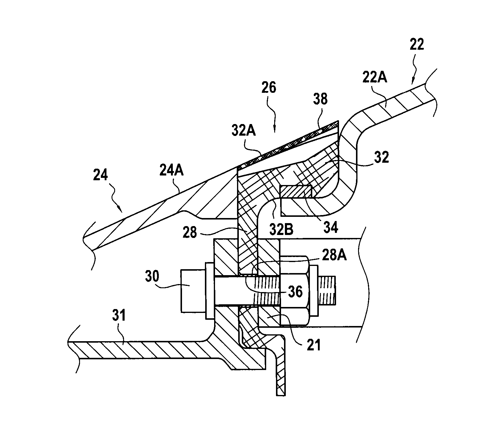
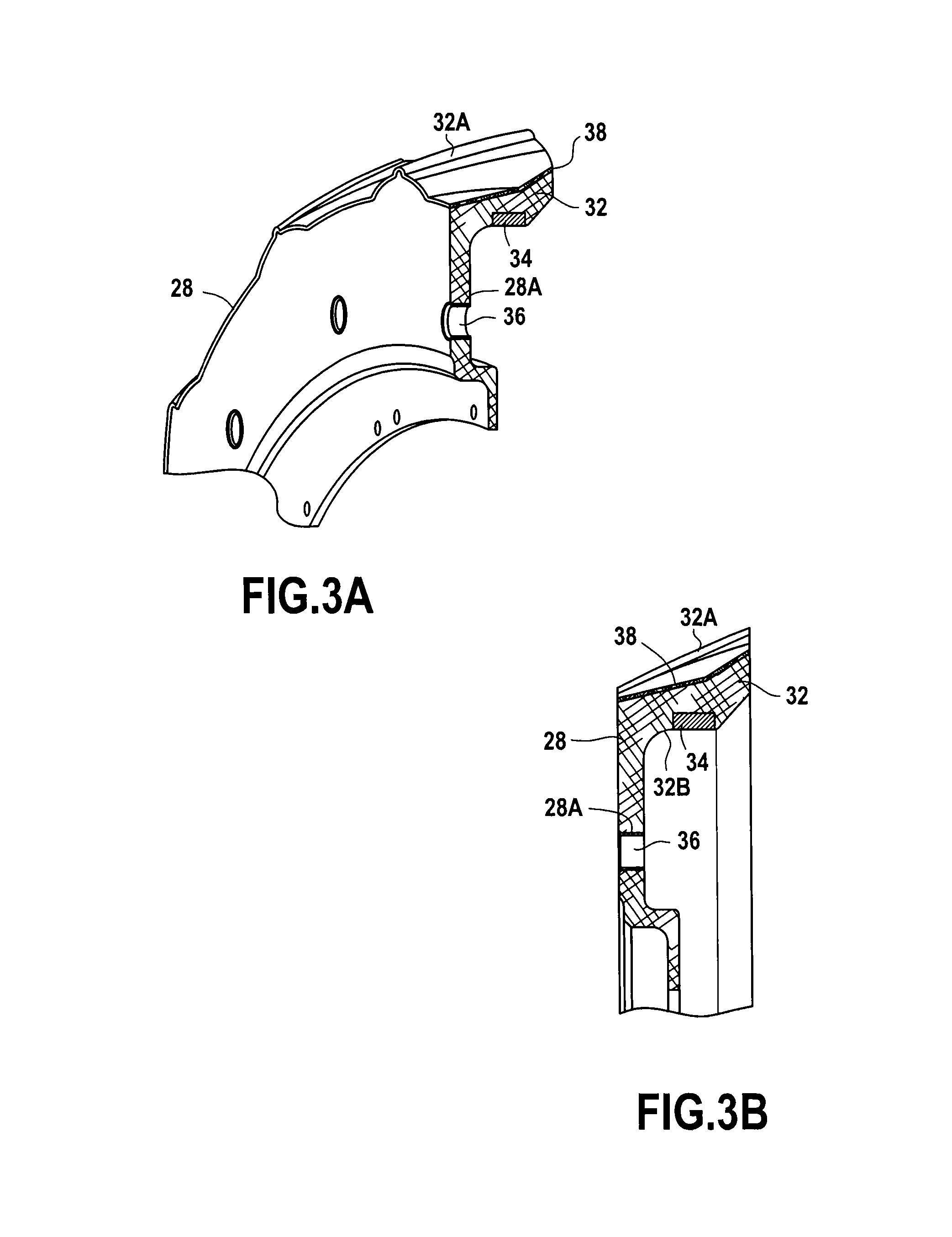
[0019]At its upstream end, the LP shaft carries a plurality of fan blades having their radially inner ends fastened in conventional manner to a fan disk (referenced 21 in FIG. 2), in contact with inter-blade platforms 22, and an inlet cone 24 is connected to these platforms carrying ...


PUM


Abstract

A link part for a turbine engine which mounted between a fan cone and a fan disk supporting fan blades is provided. The link part includes an annular wall pierced by a plurality of orifices, each orifice for receiving a fastener member and terminated by a substantially perpendicular rim having an outer surface that provides an aerodynamic extension of the fan between an outer surface of the fan cone and an outer surface of a fan blade platform. The annular wall is made of a first material that is composite and is provided on an inner surface of the rim with a ring made of a second material that is different from the first and that is suitable for radially retaining the fan blade platform.

Description

BACKGROUND OF THE INVENTION[0001]The present invention relates to the general field of aviation turbine engines, and in particular turbojets. It relates more particularly to a link part having a radial retention function, such as a fan ferrule providing mechanical and aerodynamic connection between a fan inlet cone, fan blade platforms constituting the inside of the flow section between the fan blades, and a fan disk.[0002]At its upstream end, a turbojet has an air inlet feeding a fan and a compressor having blades that are carried by disks secured to a rotor shaft that extends over a major portion of the turbojet and that is driven in rotation by a turbine of the turbojet.[0003]An inlet cone is mounted on the upstream end of this platform in order to deflect a fraction of the air stream that penetrates into the turbojet towards the fan blades, this stream subsequently being separated into a primary stream that feeds the gas generator and a secondary stream that provides the majorit...

Claims


Application Information

Patent Timeline
Patent Type & Authority Patents(United States)
IPC IPC(8): F01D5/02F02K3/06F01D5/30F04D29/32B64C11/14F04D29/64F01D5/32
CPCF01D5/02F02K3/06F04D29/321F04D29/329F04D29/644B64C11/14F01D5/3007F01D5/3015F01D5/326F04D29/325F04D29/326F04D29/646F05D2260/30F05D2300/603F04D29/023F01D5/025F02C7/04F01D5/066
Inventor LOMBARD, JEAN-PIERRE FRANCOISBALK, WOUTERPAUTARD, SEBASTIENSAMSON, BENJAMINKIENER-CALVET, BENJAMINROGUES, FREDERIC
Owner SAFRAN
Why Eureka
Try Eureka