Current-drive integrated circuit automatic wiring method and device

A current-driven, automatic wiring technology, applied in electrical digital data processing, special data processing applications, instruments, etc., can solve problems such as digital circuit wiring algorithms, avoid electromigration effects, avoid wiring obstacles, and optimize wiring overall area effect

Active Publication Date: 2013-08-07
TSINGHUA UNIV
View PDF2 Cites 9 Cited by
  • Summary
  • Abstract
  • Description
  • Claims
  • Application Information

AI Technical Summary

Problems solved by technology

Therefore, the wiring problem to avoid the electromigration effect is a wiring with variable line width, and the existing digital circuit wiring algorithm cannot be used. It is necessary to study the wiring algorithm and wiring tools for the electromigration effect.

Method used


Image

  • Current-drive integrated circuit automatic wiring method and device
  • Current-drive integrated circuit automatic wiring method and device
  • Current-drive integrated circuit automatic wiring method and device

Examples


no. 1 example

[0036] The automatic wiring method of this embodiment can avoid the electromigration effect, and the method can meet the constraints of the current on the line width, avoid wiring obstacles, satisfy Kirchhoff's law, realize automatic wiring of the wire net, and optimize the wiring area of ​​the wire net.

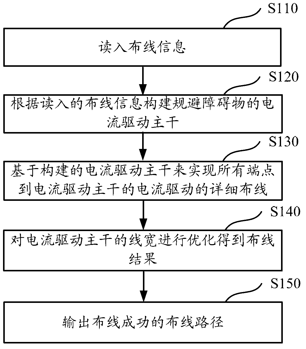
[0037] In this embodiment, the circuit netlist, current constraints, and wiring design rules are input first, and finally the wiring results are output through methods such as single-trunk topology establishment, detailed wiring, and line width optimization. figure 1 It is a schematic flow chart of the current-driven integrated circuit automatic wiring method according to the first embodiment of the present invention, and the following reference figure 1 to describe each step in detail.

[0038] In step S110, the wiring information is read in, and the wiring information includes information about the network to be wired, wiring design rules and current constraints.

[0039]...

no. 2 example

[0078] Figure 4 It is a structural schematic diagram of a current-driven integrated circuit automatic wiring device according to the second embodiment of the present invention.

[0079] Such as Figure 4 As shown, the device includes: a read-in module 41 , a trunk construction module 42 , a detailed wiring module 43 , a trunk optimization module 44 and an output module 45 .

[0080] The read-in module 41 , trunk construction module 42 , detailed wiring module 43 , trunk optimization module 44 and output module 45 of this embodiment respectively execute the operations of steps S110 , S120 , S130 , S140 and S150 of the first embodiment. It will not be expanded in detail here.

[0081] Those skilled in the art should understand that each module or each step of the present invention described above can be realized by a general-purpose computing device, and they can be concentrated on a single computing device, or distributed on a network formed by multiple computing devices, O...


PUM


Abstract

The invention discloses a current-drive integrated circuit automatic wiring method which includes a reading-in step of reading in wiring information which includes information of a network to be wired, wiring design rules and current constraint, a trunk construction step of constructing a current drive trunk for avoiding obstacles according to the read-in wiring information, a detailed wiring step of achieving detailed wiring from all end points to the current drive trunk based on the constructed current drive trunk and a trunk optimizing step of optimizing line width of the current drive trunk to obtain a wiring result. The method can meet the requirement of the current for wiring line width constraint, effectively avoids wiring obstacles and optimizes wiring total area under the condition that an electric migration effect is avoided.

Description

technical field [0001] The invention relates to the field of integrated circuit physical design, in particular to a current-driven integrated circuit automatic wiring method and device. Background technique [0002] As integrated circuits enter the nanotechnology process, the operating current of integrated circuits continues to increase, while the feature size of chips continues to decrease, so that the current flowing per unit area on the metal interconnection, that is, the current density, continues to increase, resulting in metal The phenomenon of electromigration is becoming more and more serious. Although most of the advanced integrated circuit wiring technology adopts copper technology, compared with the early aluminum technology, the use of copper technology can greatly improve the metal electromigration effect. Very serious, because the large working current and insufficient line width will lead to the occurrence of electromigration, resulting in short circuit or o...

Claims


Application Information

Patent Timeline
Patent Type & Authority Applications(China)
IPC IPC(8): G06F17/50
Inventor 张骥骅姚海龙
Owner TSINGHUA UNIV
Why Eureka
Try Eureka