Traveling device and power limiting mechanism

a technology of power limiting mechanism and traveling device, which is applied in the direction of toys, clutches, automatic clutches, etc., can solve the problems of difficulty in mounting the power limiting mechanism, and achieve the effect of reducing the installation space and reducing the size of the power limiting mechanism

Inactive Publication Date: 2006-02-02
KONAMI DIGITAL ENTERTAINMENT CO LTD
View PDF20 Cites 31 Cited by
  • Summary
  • Abstract
  • Description
  • Claims
  • Application Information

AI Technical Summary

Benefits of technology

[0008] According to this running device, since the left and right wheels are driven by the left and right driving sources respectively, it is necessary to provide the power transmitting mechanism for each wheel. If each power transmitting mechanism is to be provided with a power limiting mechanism, it is impossible to downsize the running device because th...

Problems solved by technology

However, since the conventional power limiting mechanism is provided at some midpoint in gear train or the like constituting the power transmitting mechanism, it is difficult to mount the power limiting mechanism if there is not enough insta...

Method used


Image

  • Traveling device and power limiting mechanism
  • Traveling device and power limiting mechanism
  • Traveling device and power limiting mechanism

Examples


Embodiment Construction

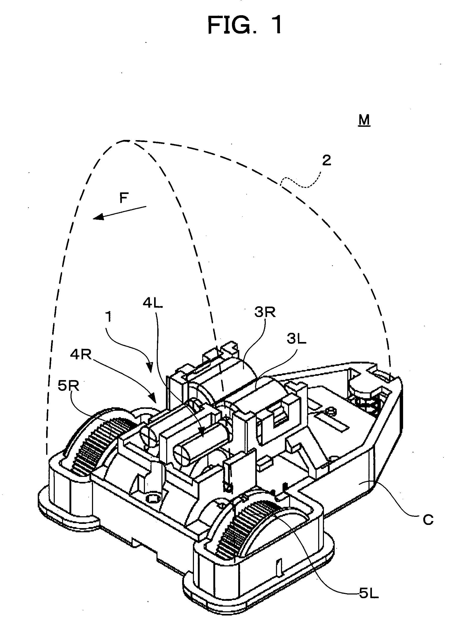
[0020]FIG. 1 shows an internal structure of a model M in which a running device used in one embodiment for carrying out the invention is incorporated. The model M includes a chassis C, a running device 1 mounted on the chassis C, and a cover 2 for covering the chassis C. The cover 2 is modeled after a character, an animal or the like, and the arrow F in FIG. 1 shows a frontward direction of the model M.

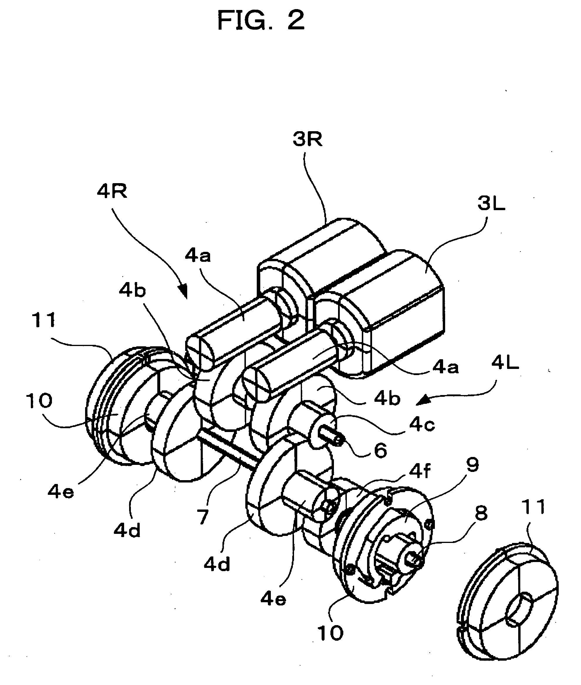
[0021] The running device 1 includes a pair of left and right motors 3L and 3R as power sources, power transmitting mechanisms 4L and 4R for respectively transmitting powers from the motors 3L and 3R, and wheels 5L and 5R which are rotated by the powers transmitted by the power transmitting mechanisms 4L and 4R. As shown in FIG. 1, the motors 3L and 3R are mounted on the upper portion of the chassis C in a state in which the motors 3L and 3R are arranged side-by-side in the lateral direction. The power transmitting mechanisms 4L and 4R are laterally symmetric, and the wheels 5L and 5...


PUM


Abstract

A running device (1) for transmitting a power from a power source (3L, 3R) to an axle (8) through a power transmitting mechanism (4L, 4R) to rotate a wheel (5L, 5R) which is connected to the axle (8), wherein the wheel includes a power limiting mechanism (9, 10) to limit a torque transmitted between the wheel (5L, 5R) and the axle (8).

Description

TECHNICAL FIELD OF THE INVENTION [0001] The present invention relates to a running device and a power limiting mechanism used for a model and the like. BACKGROUND ART OF THE INVENTION [0002] In a running device which transmits a torque from a power source to a wheel through a power transmitting mechanism including a worm, a worm wheel and the like, in order to prevent a gear of the power transmitting mechanism from being damaged when a large external force is applied to the wheel, a power limiting mechanism is conventionally provided for controlling the torque transmitted to the power transmitting mechanism from the wheel (see Japanese Patent No. 2834678). SUMMARY OF THE INVENTION [0003] However, since the conventional power limiting mechanism is provided at some midpoint in gear train or the like constituting the power transmitting mechanism, it is difficult to mount the power limiting mechanism if there is not enough installation space of the power transmitting mechanism. Thereupo...

Claims


Application Information

Patent Timeline
IPC IPC(8): F16D7/04A63H17/26A63H17/36A63H17/42A63H31/00F16D43/202
CPCA63H17/262A63H17/264A63H17/36F16D43/2028A63H31/00F16D7/048A63H17/42
Inventor SAEKI, KAZUYUKIHAYASHI, RYOJI
Owner KONAMI DIGITAL ENTERTAINMENT CO LTD
Why Eureka
Try Eureka