

Rotation angle detecting device
a detection device and rotation angle technology, applied in measurement devices, instruments, using electrical means, etc., can solve problems such as detection errors of rotation angles, and achieve the effect of improving rotation angle detection
- Summary
- Abstract
- Description
- Claims
- Application Information
AI Technical Summary
Benefits of technology
Problems solved by technology
Method used
Image

Examples
Embodiment Construction
[0017] A rotation angle detecting device according to the first embodiment of the invention will be described with reference to FIGS. 1-5 of the appended drawings.
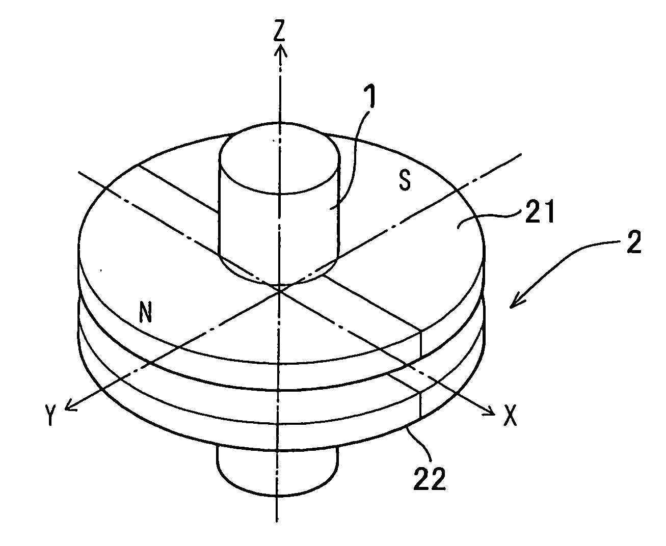
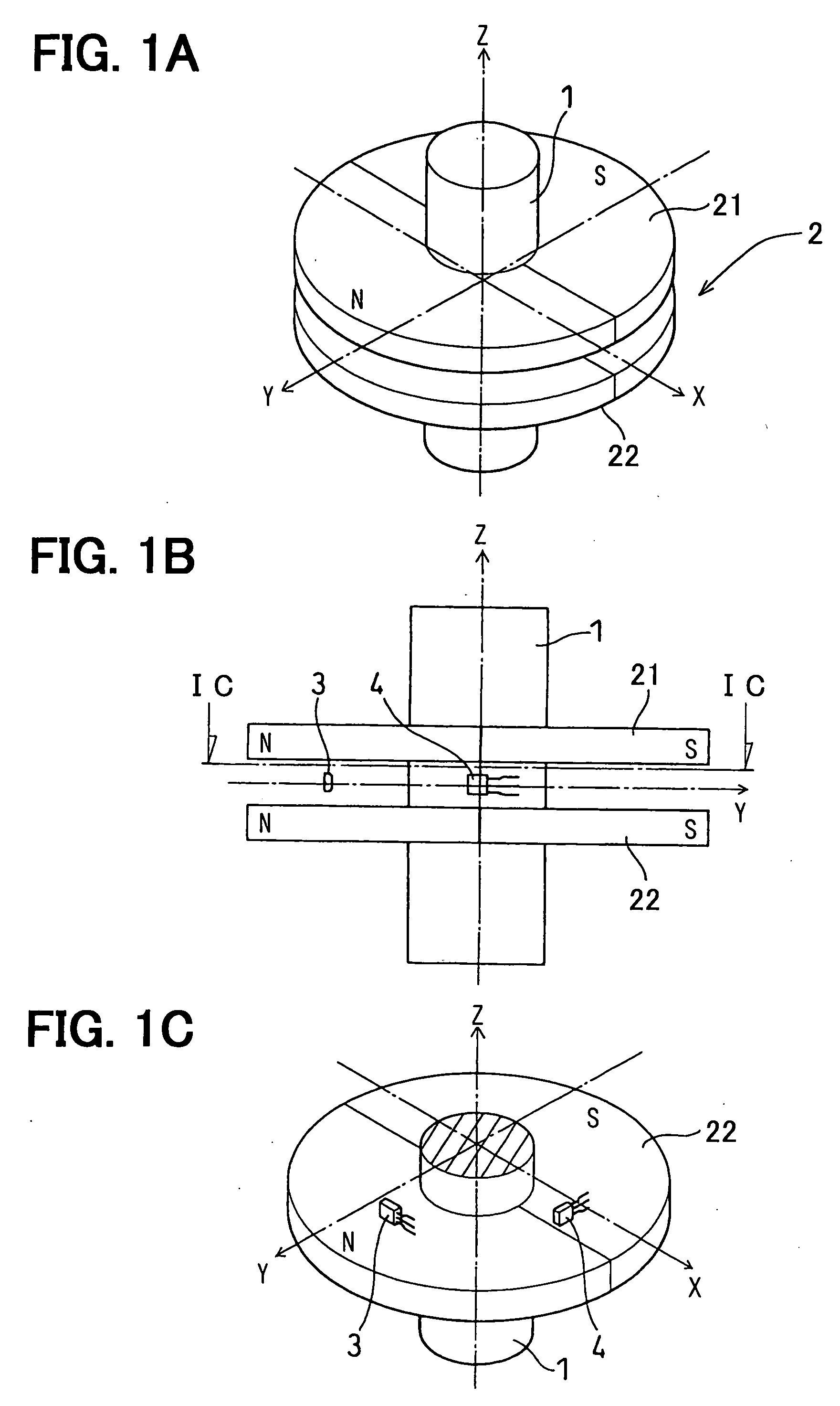
[0018] The rotation angle detecting device includes a shaft 1, a permanent magnet unit 2, a pair of magnetic sensors 3, 4 and an angle processing unit 5. The shaft 1 is a pole member made of a magnetic material such as iron and is connected to an outside member such as a rotating shaft of a throttle valve. The permanent magnet unit 2 is constituted of a pair of magnet disks 21, 22, which are supported by the shaft 1 at a certain distance in the axial direction to rotate together therewith. The magnet disks 21, 22 have an axis Z and a pair of radially magnetized magnetic poles N, S at opposite positions (at an interval of 180 degrees) on its periphery. The magnet disks 21, 22 are the same both in size and magnetic characteristics. Accordingly, a closed magnetic field is formed in the space around the shaft 1 between the ma...
PUM
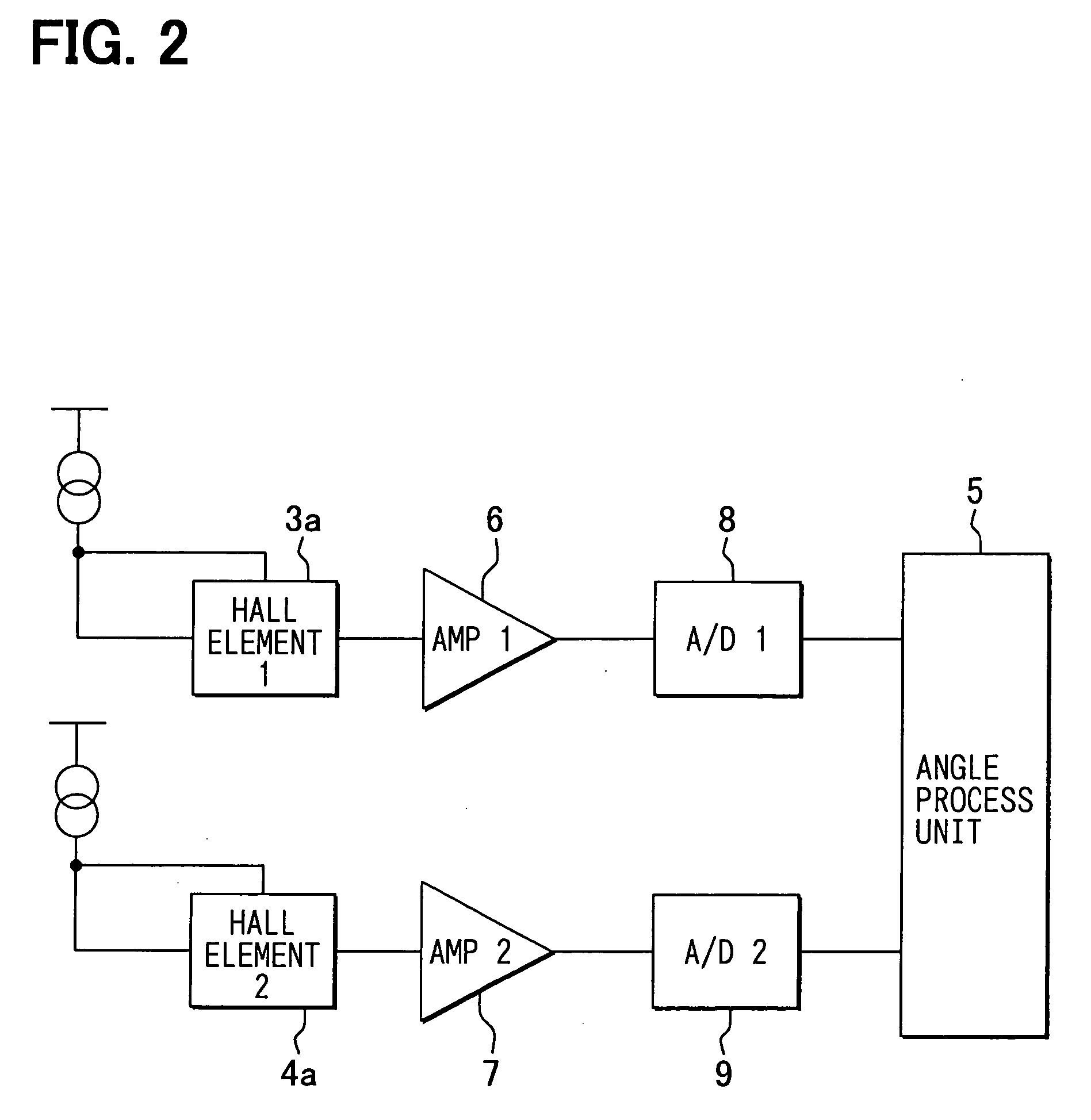
 Abstract
Description
Claims
Application Information