Implementation method for detaching TBM in tunnel

An implementation method and technology of content, applied in the field of dismantling TBM in the hole, can solve the problems of small contact surface, damage of track and cable tray frame, poor stability, etc.

Active Publication Date: 2020-07-31
SINOHYDRO BEREAU 10 CO LTD
View PDF14 Cites 3 Cited by
  • Summary
  • Abstract
  • Description
  • Claims
  • Application Information

AI Technical Summary

Problems solved by technology

[0005] At the same time, the following factors affect the sliding of the TBM rear supporting system on the R120-meter arc section: (1) the span of the two sets of sliding wheels at the front and rear of each trolley, and the rolling friction between the sliding wheels and the track support (2) The sliding track and cable tray frame of the segment crane are installed between the trolleys. If the TBM is equipped to slide on the R120-meter arc segment, the track and cable tray frame will be subjected to bending pressure and be broken. Damage; (3) The segment feeding machine is 19 meters long, 2.4 meters wide, and 0.48 meters high. It is suspended under the trolley through four zippers and slides synchronously with the trol

Method used


Image

  • Implementation method for detaching TBM in tunnel
  • Implementation method for detaching TBM in tunnel
  • Implementation method for detaching TBM in tunnel

Examples


Embodiment approach

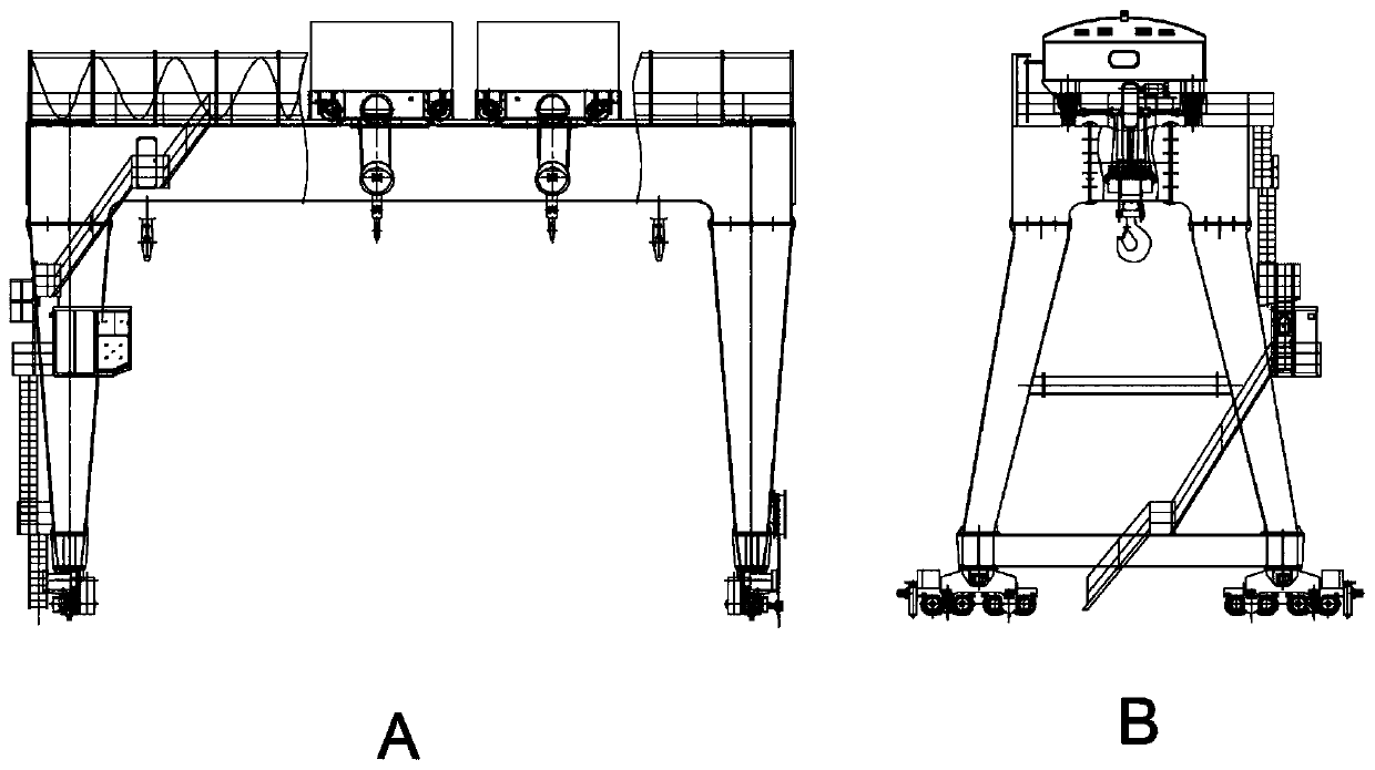
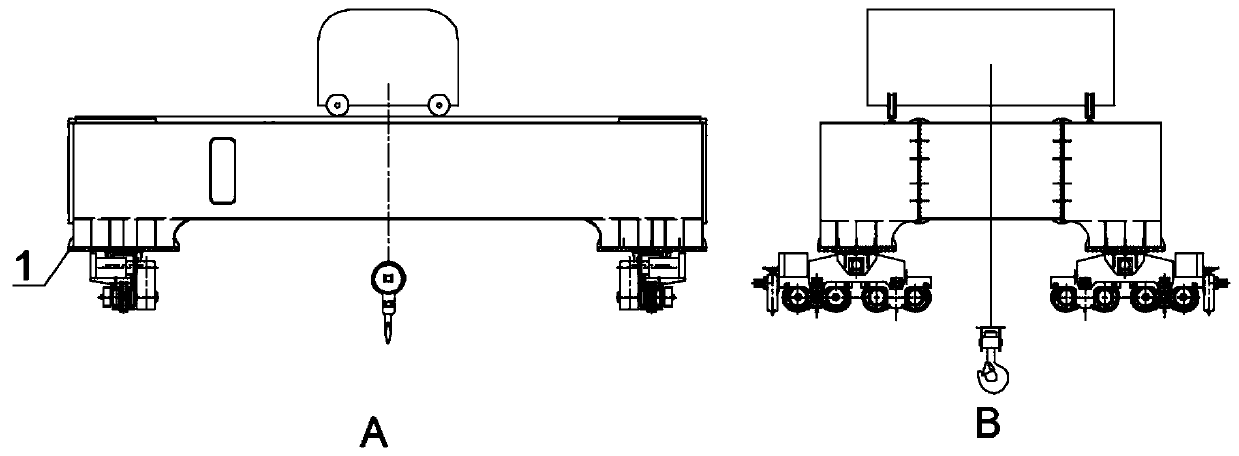
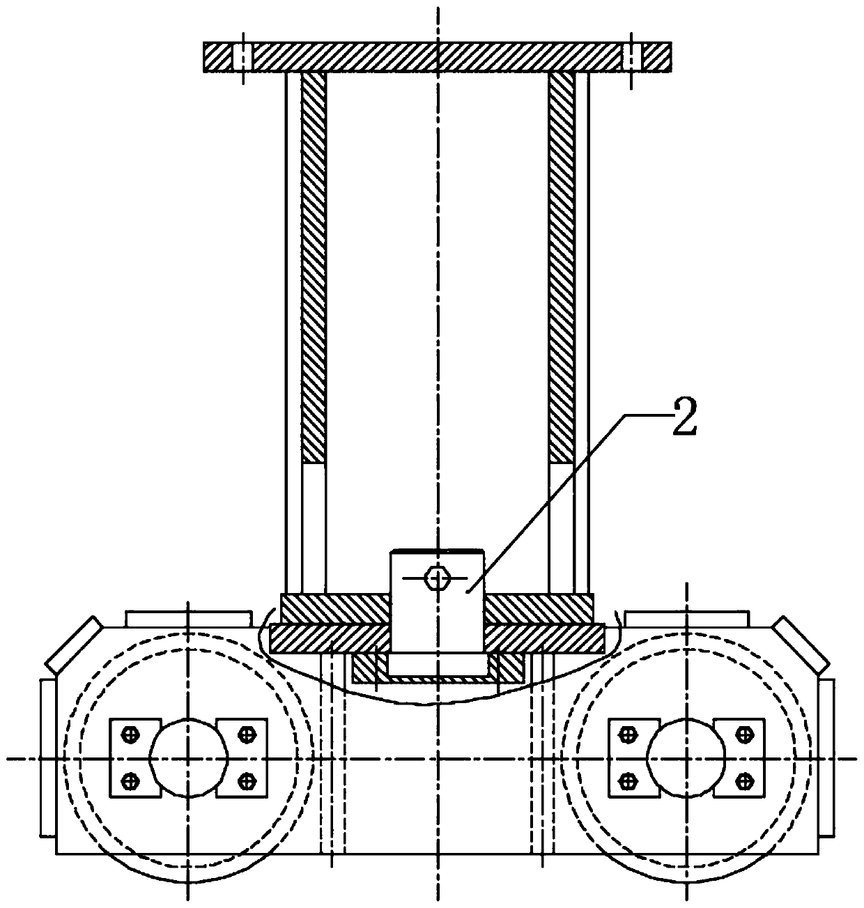
[0025] Such as figure 1 , figure 2 and image 3 As shown, the implementation method of disassembling the TBM in the hole involved in the present invention includes the following contents:

[0026] Arrange the dismantling chamber;

[0027] After the TBM excavation is completed, separate the TBM shield body and the rear support from the traction cylinder, and then slide to the dismantling chamber respectively;

[0028] Shield taxiing: Lay track I, introduce power and cooling water, transform the hydraulic pump station of the advanced drilling system, and connect with the high-pressure oil pipe of the oil cylinder at the inner bottom of the tail shield to complete the propulsion of the TBM shield on the track;

[0029] Back supporting sliding: the connection structure between the trolleys of the supporting sliding system after disassembly, each trolley includes road wheels, lower wheel frames and upper wheel frames. On the upper part of the lower wheel frame, newly install t...


PUM


Abstract

The invention discloses an implementation method for detaching a TBM in a tunnel. The implementation method comprises the following steps of arranging a detaching chamber; after TBM tunneling is finished, separating a TBM shield body and a rear supporting facility from a traction oil cylinder, and then making the TBM shield body and the rear supporting facility slide to the detaching chamber separately; making the shield body slide; making the rear supporting facility slide; laying a track II, then installing a winch, and utilizing the winch for enabling all sections of a trolley to slide on the tack; arranging an overhead crane at the top of the detaching chamber; after the shield body slides to the detaching chamber, utilizing the overhead crane for detaching a cutterhead, a main drive and a supporting jack of the shield body in sequence; and after the rear supporting facility slides to the detaching chamber, detaching equipment on the trolley, and disassembling the trolley. According to the implementation method for detaching the TBM in the tunnel, the TBM shield body and the rear supporting facility are separated from the traction oil cylinder and then slide to the detaching chamber separately, then dynamic electricity and cooling water are introduced, and a hydraulic power station of an advanced bore system is transformed to be connected with a high-pressure oil pipe of anoil cylinder in a tail shield to finish advancing of the shield body; and meanwhile, a rotatable wheel carrier is adopted so that the trolley can slide on an arc section.

Description

technical field [0001] The invention relates to the technical field of tunnel construction, in particular to an implementation method for dismantling a TBM in a tunnel. Background technique [0002] 94.1% of the tunnel sections were excavated by two TBMs at the same time, and 5.9% of the tunnel sections were excavated by the drill and blast method. One of the two TBMs enters the main tunnel directly from the exit of the water delivery tunnel, and exits from the sliding branch tunnel. The bottom elevation of the sliding branch tunnel entrance is 1260m, and the total length is 1360m. It is a downhill tunnel and intersects with the water delivery tunnel. [0003] Principles of sliding branch tunnel layout: ①Considering the needs of later dismantling, the turning radius in the tunnel is not less than 70m, comprehensively considering the needs of TBM sliding, the turning radius at the end of the sliding branch tunnel is adjusted to 120m; ②The width of the tunnel is widened on bo...

Claims


Application Information

Patent Timeline
IPC IPC(8): E21D9/087E21D9/06E21F13/00
CPCE21D9/0621E21D9/087E21F13/006
Inventor 李超唐洪应陈国贵刘毓川周长虹李明孟凡朋李宗宗曾金
Owner SINOHYDRO BEREAU 10 CO LTD
Why Eureka
Try Eureka