Microstructure containing entities rotating under an applied load to enhance toughening against fracture

a microstructure and entity technology, applied in the field of composite materials having a microstructure model, can solve the problems of increasing the cost of composite production, entity or additive has in most cases lost its ability, and inefficient techniques, so as to reduce the amount of strain energy available, reduce the intensity of induced stress, and reduce the effect of strain energy promoting fractur

Inactive Publication Date: 2006-01-03
KENNEFICK CHRISTINE M
View PDF1 Cites 5 Cited by
  • Summary
  • Abstract
  • Description
  • Claims
  • Application Information

AI Technical Summary

Benefits of technology

[0011]The rotational movement gives rise to strain in the surrounding matrix whose associated elastic stresses form alternating regions of compression and tension. The alternating regions of compression and tension can add to existing stresses in such a way as to reduce strain energy promoting fracture. Additionally, the alternating regions of tension and compression can serve as initial conditions for vibrations in the atomic lattice of the material that will absorb energy. The absorption of energy from the vibrations is also expected to reduce the amount of strain energy available for release from the propagation of a crack.
[0012]It is another object of the present invention to provide a microstructure whose stresses that are used to prevent fracture actually respond to an applied load and increase as the applied load gets larger. This requires the microstructure to include entities which actually interact with nearby cracks, pores and flaws so as to stop cracks and to counteract associated flaws arising therefrom. A primary objective of the invention is to stop cracks from moving rather than having them deflect around various microstructural entities or additives. Moreover, as an applied load is increased, the angle of rotation increases, with a subsequent increase in the intensity of the induced stresses from strain in the matrix material. The degree of counteraction to built up strain energy from the applied load is therefore expected to increase.
[0013]It is a further object of this invention to utilize a relatively simple microstructure entity configuration, which in a preferred embodiment, may include grains and particles that can be patterned primarily through heating and cooling, in addition to making use advantageously of subsequent pores and microcracks that arise naturally. By having a microstructure with the entities being grains or particles set into a matrix material, the present invention avoids the necessary fiber architectures, coatings or phase transformation of the prior art that increase costs of manufacturing and fabrication. The present invention also eliminates the lengthy fabrication processes of the prior art associated with the aforementioned well-known techniques.

Problems solved by technology

Although these residual stresses may be set once fabrication or a phase transformation is completed, they might be attenuated by a large applied load itself before they can negate part of the concentrated stress around a crack tip, thereby making such techniques inefficient.
Furthermore, the layup of composites comprising fibers, coating and laminates in lightweight ceramics and intermetallics involves several process steps, thereby increasing the cost of producing the composite.
Another problem with the prior art is that once a crack has passed a particular entity or additive, however, such entity or additive has in most cases lost its ability through unloading to interact with or deflect other cracks.

Method used


Image

  • Microstructure containing entities rotating under an applied load to enhance toughening against fracture
  • Microstructure containing entities rotating under an applied load to enhance toughening against fracture
  • Microstructure containing entities rotating under an applied load to enhance toughening against fracture

Examples


Embodiment Construction

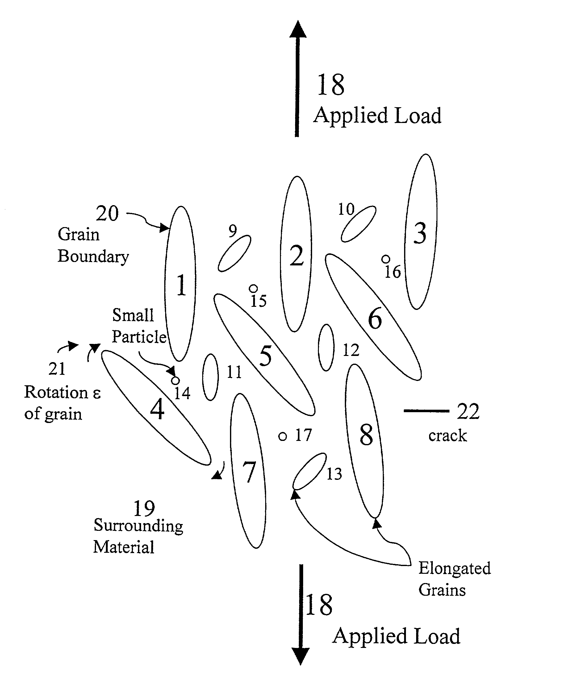
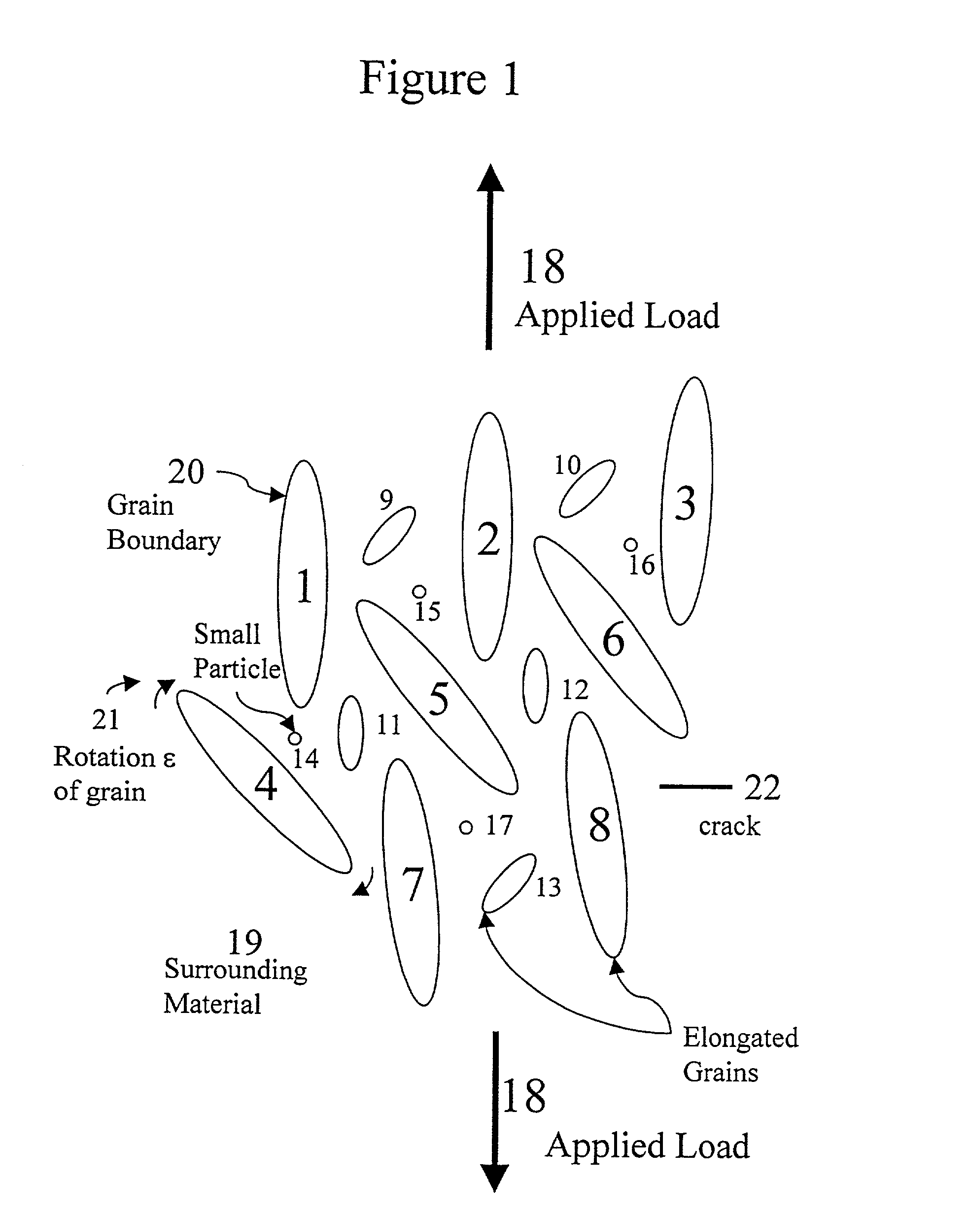
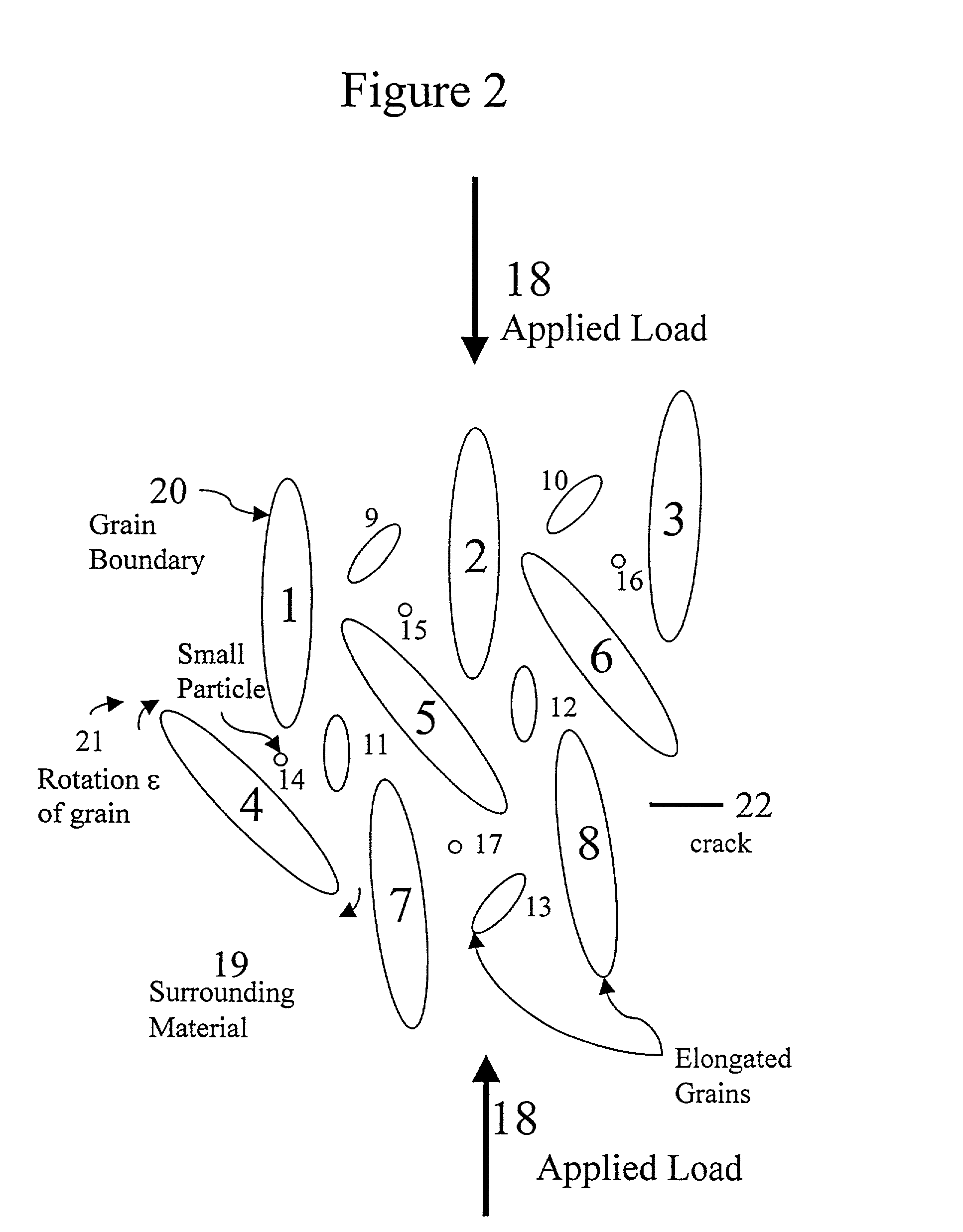
[0017]The present invention will now be described in greater detail with reference to the accompanying drawings. Referring to FIG. 1, an external or remotely applied tensile stress or load 18 is exerted upon elliptically-shaped microstructure entities or particles 1 through 17, each of which will rotate in its surrounding matrix material 19. Although microstructural entities 8 and 13 are specifically labeled as elongated grains and entity 14 as a small particle, microstructural entities 1 through 13 are similarly elongated grains and entities 14 through 17 are small particles in both FIGS. 1 and 2. As the applied load increases, an angle of rotation increases as do the induced stresses both in the matrix material and in the particles. In practice, the material discontinuity giving rise to the rotation can be a difference in the bonding and elastic properties at the particle-matrix boundary 20 itself or across the boundary.

[0018]Particles 14 to 17 may be smaller than entities 1 throu...


PUM

PropertyMeasurementUnit
compressiveaaaaaaaaaa
tensile stressaaaaaaaaaa
strain energyaaaaaaaaaa

Abstract

A composite material having a microstructure model is provided with a continuous matrix of microstructure entities such as particles and grains that rotate under both remotely applied stresses and induced concentrated stresses from nearby cracks, pores and smaller particles, all networked within the matrix. The rotation microstructure entities are smooth closed contours that are elliptically-shaped. A net moment results on the boundaries of the microstructure entities effecting fracture toughening of the material. Small particles and other microstructural entities may reduce the attenuation of, transmit, and counteract the stresses induced by the rotating microstructure entities. The induced stresses counteract those stresses and strain energy densities that promote crack propagation. The result is a microstructure free of laminates, coatings, fibers and fiber architectures that effect toughening of the material against fracture.

Description

RELATED APPLICATION[0001]This application is a continuation-in-part (CIP) application of U.S. application Ser. No. 09 / 164,363, filed on Oct. 1, 1998, which is a continuation-in-part (CIP) of U.S. application Ser. No. 08 / 805,466 filed Feb. 25, 1997, now U.S. Pat. No. 5,826,213 issued Oct. 20, 1998.[0002]The present invention was made with Government support from an American Society for Engineering Education Fellowship.BACKGROUND OF THE INVENTION[0003]1. Field of the Invention[0004]The present invention is directed to a composite material having a microstructure model with properties to improve fracture toughening, and in particular to a microstructure model including entities that rotate under both an applied load and additional induced loads in order to counteract, deflect and prevent crack propagation from moving throughout the material.[0005]2. Discussion of the Related Art[0006]This invention pertains to subject matter disclosed in U.S. Pat. No. 5,826,213, the text of which is he...

Claims


Application Information

Patent Timeline
Patent Type & Authority Patents(United States)
IPC IPC(8): G06F17/50G06F17/10G06G7/48G01N3/00G01N3/02G06F17/40
CPCG06F17/5009G01N2203/0066G06F2217/16G01N2203/0214G06F30/20G06F2111/10
Inventor KENNEFICK, CHRISTINE M.
Owner KENNEFICK CHRISTINE M
Why Eureka
Try Eureka