Optical device, display device, and three-dimension image display device

Inactive Publication Date: 2006-02-23
RICOH KK
View PDF22 Cites 50 Cited by
  • Summary
  • Abstract
  • Description
  • Claims
  • Application Information

AI Technical Summary

Benefits of technology

[0024] A more specific object of the present invention is to provide an optical element and an optical device able to change a polarization state in time order and to produce polarized light with little wavelength dependence and superior in polarization purity, a display device able to perform pixel shift easily and accurately to

Problems solved by technology

In the pixel shift technique, which involves oscillation of the image display units or the optical elements, because mechanical oscillation occurs at the same time, durability of the image display units or the optical elements is degraded, and heat or noise is generated.
In contrast, the pixel shift technique employing liquid crystal optical deflection elements is superior in mechanical reliability, but if liquid crystal alignment is not sufficient, the contrast of images can be degraded, and due to this, cost of each display element may increase.
However, because mechanical oscillation occurs in the display device

Method used


Image

  • Optical device, display device, and three-dimension image display device
  • Optical device, display device, and three-dimension image display device
  • Optical device, display device, and three-dimension image display device

Examples


first embodiment

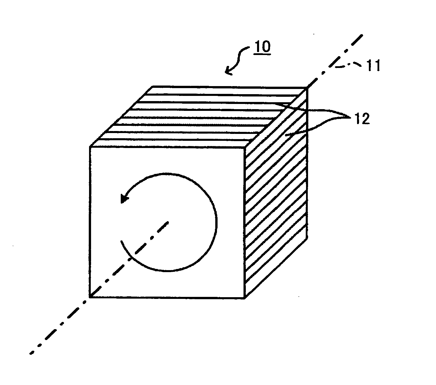
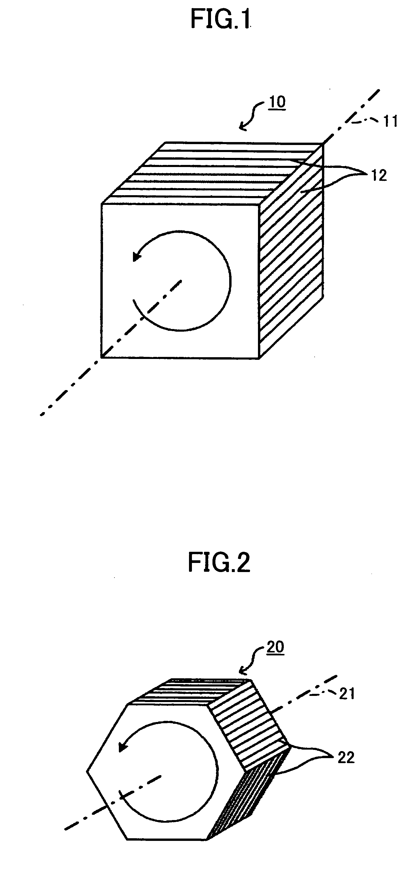
[0167]FIG. 1 is a perspective view of an optical element according to a first embodiment of the present invention.

[0168] As illustrated in FIG. 1, an optical element 10 is formed from a quadrangular prism having a rotational axis 11 and four side surfaces 12. The four side surfaces 12 of the quadrangular prism are translucent and are parallel to the rotational axis 11. At least a portion of the surfaces 12 is formed from an optically anisotropic medium which switches, in time order, a polarization state of a light beam transmitting through the surfaces 12 along with rotation of the optical element 10, and emits the light beam.

[0169]FIG. 2 is a perspective view of another example of the optical element according to the present embodiment of the present invention.

[0170] As illustrated in FIG. 2, an optical element 20 is formed from a hexagonal prism having a rotational axis 21 and six side surfaces 22. The six side surfaces 22 of the hexagonal prism are translucent and are parallel...

second embodiment

[0264]FIG. 21 is a cross sectional view of an optical element according to a second embodiment of the present invention.

[0265] As illustrated in FIG. 21, in an optical element 70, a number of polarizers 71 are arranged alternately, which have transmission axes in the vertical (V) direction and in the horizontal (H) direction, and Red, Green, and Blue color filters are on the polarizers 71 in order, thus resulting in six combinations of polarization directions and colors. These color filters and polarizers 71 are arranged along the circumferential region of the optical element 70. The structure including the color filters and the polarizers 71 forms an optically anisotropic medium of the optical element 70.

[0266] When the optical element 70 is rotated, the outgoing light beam from the optical element 70 changes in polarization-color state thereof through time among the following ones, that is, a vertically-linear-polarized red light beam (indicated as “R-V”), a horizontally-linear-...


PUM


Abstract

An optical element, an optical device, and a display device are disclosed that are able to change a polarization state in time order and to produce polarized light with little wavelength dependence and superior in polarization purity, and able to perform pixel shift easily and accurately to realize high resolution image display. The optical element has a translucent surface parallel to the rotational axis of the optical element, and at least a portion of the translucent surface is formed from an optically anisotropic medium. A polarization state of a light beam transmitting through the translucent surface is switched in time order along with rotation of the optical element.

Description

BACKGROUND OF THE INVENTION [0001] 1. Field of the Invention [0002] The present invention relates to an optical element, an optical element, a display device, and a three-dimension image display device, and more particularly, to a technique employed by a projection display device, especially, a projection display device using a digital micro-mirror device (abbreviated to be “DMD”) for increasing the resolution of the projection display device. [0003] 2. Description of the Related Art [0004] In a so-called “pixel shift technique”, a pixel shift element is used to display image patterns, with display positions of them being shifted by using an optical deflection element in response to deflection of the light path in each sub-field, and thereby, the number of pixels of image display units appears to be doubled. The pixel shift element includes plural image display units arranged two-dimensionally and being controllable according to image information, a light source that emits light to ...

Claims


Application Information

Patent Timeline
IPC IPC(8): G02B5/30
CPCG02B5/3083G02B27/286G02B27/26G02B30/25
Inventor TOKITA, TOSHIAKIFUJITA, KAZUHIROMURAI, TOSHIHARUTAKAURA, ATSUSHIMIYAGAKI, KAZUYAOSAKA, TAKANOBUTAKIGUCHI, YASUYUKISUGIMOTO, HIROYUKIMATSUKI, YUMIHIRANO, YUKIKO
Owner RICOH KK
Why Eureka
Try Eureka