Metal heating apparatus, metal heating method, and light source apparatus

a heating method and metal technology, applied in the direction of ohmic-resistance heating, manufacturing tools, solventing apparatus, etc., can solve the problems of difficult for conventional devices to perform efficient heating, and achieve the effect of simple and inexpensive, optimal heating, and simple and inexpensiv

Inactive Publication Date: 2012-11-06
SUMITOMO ELECTRIC IND LTD
View PDF25 Cites 1 Cited by
  • Summary
  • Abstract
  • Description
  • Claims
  • Application Information

AI Technical Summary

Benefits of technology

[0009]An object of the present invention is therefore to provide a metal heating apparatus, a metal heating method, and a light source apparatus capable of performing efficient heating according to each object.
[0038]In the metal heating method according to the present invention, preferably, the first metal member comprises gold as a primary component and the first center wavelength is less than 600 nm. Preferably, the second metal member comprises tin as a primary component and the second center wavelength is not less than 600 nm. The second metal member is preferably a solder. In this case, the first metal member is compatible in soldering with the solder being the second metal member. Since the reflectance of gold is low at the center wavelengths of less than 600 nm, the first metal member can be efficiently heated when the light of the center wavelength of less than 600 nm is applied onto the first metal member comprising gold as a primary component. Since a relatively inexpensive light source with high output power is available as a light source for outputting light of the center wavelength of not less than 600 nm and since the wavelength dependence of reflectance of tin is insignificant, the application of the light of the center wavelength of not less than 600 nm is advantageous to the second metal member comprising tin as a primary component.

Problems solved by technology

It was, however, difficult for the conventional devices to perform efficient heating according to each object.

Method used


Image

  • Metal heating apparatus, metal heating method, and light source apparatus
  • Metal heating apparatus, metal heating method, and light source apparatus
  • Metal heating apparatus, metal heating method, and light source apparatus

Examples


first embodiment

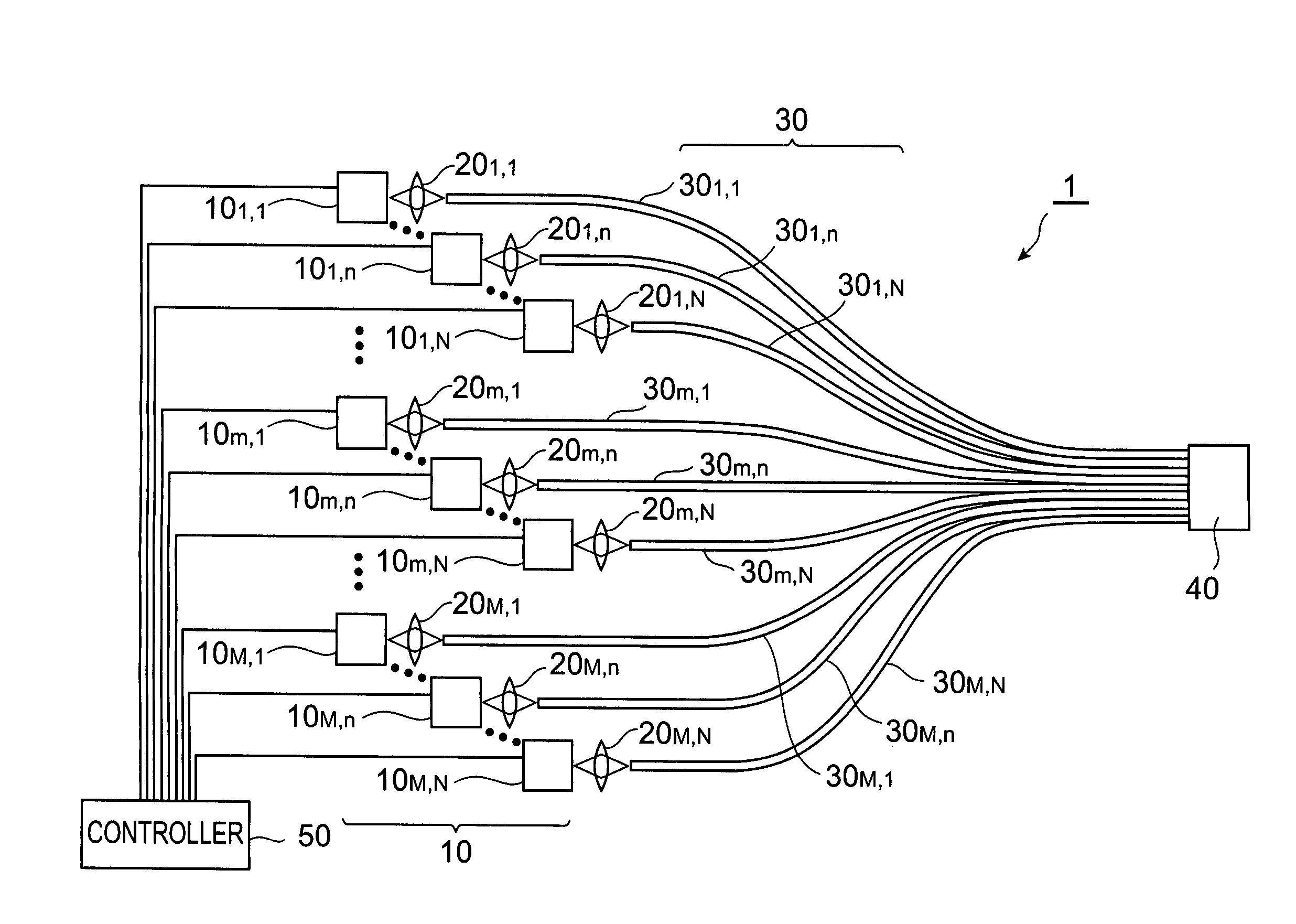
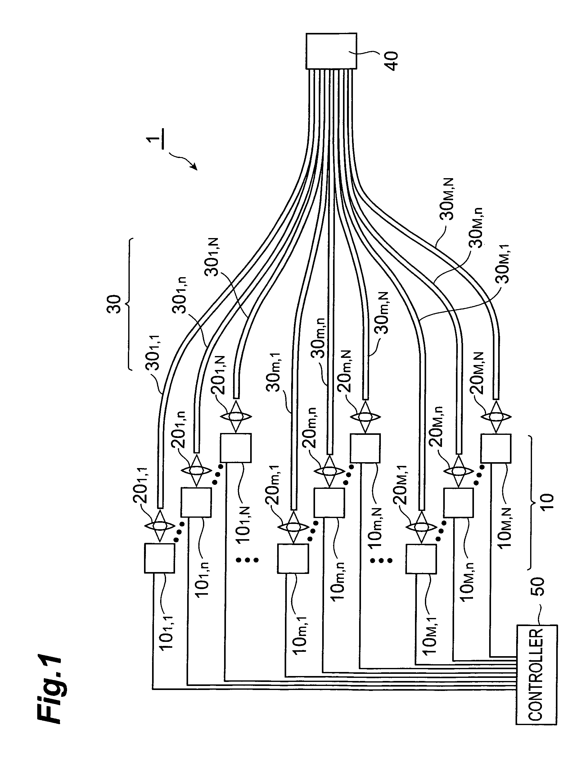
[0059]First, the first embodiment of the metal heating apparatus according to the present invention will be described. FIG. 1 is a configuration diagram of the metal heating apparatus according to the first embodiment. The metal heating apparatus 1 shown in this figure has a light output portion 10, M×N lenses 201,1-20M,N, a light guide portion (light guiding means) 30, a securing member 40, and a controller 50. Here M and N are integers of not less than 2. Furthermore, m used hereinafter indicates an arbitrary integer of not less than 1 nor more than M, and n an arbitrary integer of not less than 1 nor more than N.

[0060]The light output portion 10 has M×N light sources 101,1-10M,N. Each light source 10m,n preferably outputs light having the center wavelength in the center wavelength range of 200 nm to 600 nm. The light is further preferably a laser beam. Here, the center wavelength is a center wavelength in a wavelength width, and the wavelength width is a half-width.

[0061]A light ...

second embodiment

[0077]Next, the second embodiment of the present invention will be described. FIG. 3 is a configuration diagram of a metal heating apparatus according to the second embodiment. The metal heating apparatus 2 shown in this figure has a light output portion 10, K lenses 201 to 20K, a light guide portion (light guiding means) 30, and a controller 50. Here K is an integer of not less than 2. Furthermore, k used hereinafter indicates an arbitrary integer of not less than 1 nor more than K.

[0078]The light output portion 10 has K light sources 101 to 10K. Each light source 10k preferably outputs light having the center wavelength in the wavelength range of 200 nm to 600 nm. The light is further preferably a laser beam. Each light source 10k can be one similar to the aforementioned light source 10m,n.

[0079]The light guide portion 30 has K optical fibers 301 to 30K, and one optical fiber 31. Each lens 20k condenses light emitted from a corresponding light source 10k and injects the light into...

third embodiment

[0086]The third embodiment of the present invention will be described below. FIG. 6 is an illustration to illustrate a soldering method according to the third embodiment. A metal heating method according to the third embodiment is a method of supplying a solder (second metal member) 112 onto a metal member (first metal member) 111 and melting the solder 112 on the metal member 111 to effect soldering. In this metal heating method, laser light L is applied onto both of the metal member 111 and solder 112 or onto the metal member 111 only. When the laser light L is applied in this manner, it first melts the part facing the metal member 111, in the solder 112 placed on the metal member 111, i.e., the part of the solder 112 in contact with the metal member 111. The yield and reliability of soldering are enhanced when the part facing the metal member 111, in the solder 112 placed on the metal member 111 is melted ahead of the part opposite to the facing part, as described above.

[0087]In ...


PUM

PropertyMeasurementUnit
wavelength rangeaaaaaaaaaa
center wavelengthaaaaaaaaaa

Abstract

A metal heating apparatus according to an embodiment of the present invention comprises a light output portion for outputting light having a center wavelength in a wavelength range of 200 nm to 600 nm.

Description

CROSS-REFERENCE TO RELATED APPLICATION[0001]This application claims priority to Provisional Application Ser. No. 60 / 556,376 filed on Mar. 26, 2004 and a Provisional Application filed on Jun. 29, 2004 of which application Ser. No. 60 / 583,357 and of which title is a soldering method, which are hereby incorporated by reference in their entirety.BACKGROUND OF THE INVENTION[0002]1. Field of the Invention[0003]The present invention relates to a metal heating apparatus, a metal heating method, and a light source apparatus.[0004]2. Related Background Art[0005]There are a variety of devices for heating metal. For example, soldering is performed by heating with a heater, and by heating by laser beam irradiation as well.[0006]Laser beams of wavelengths from the far infrared region to the long-wavelength visible region have been used heretofore in order to heat a solder by laser beam irradiation, as described in Japanese Utility Model Laid-Open No. 5-18751 or in Masayuki Ikeda “Laser Engineerin...

Claims


Application Information

Patent Timeline
Patent Type & Authority Patents(United States)
IPC IPC(8): C22F3/00
CPCB23K1/0056B23K1/19B23K26/0608H05B3/0061
Inventor YAMADA, EIICHIROKOHDA, HIROSHISUGANUMA, HIROSHIINOUE, AKIRASAITO, KAZUHITONAKAZATO, KOJI
Owner SUMITOMO ELECTRIC IND LTD
Why Eureka
Try Eureka