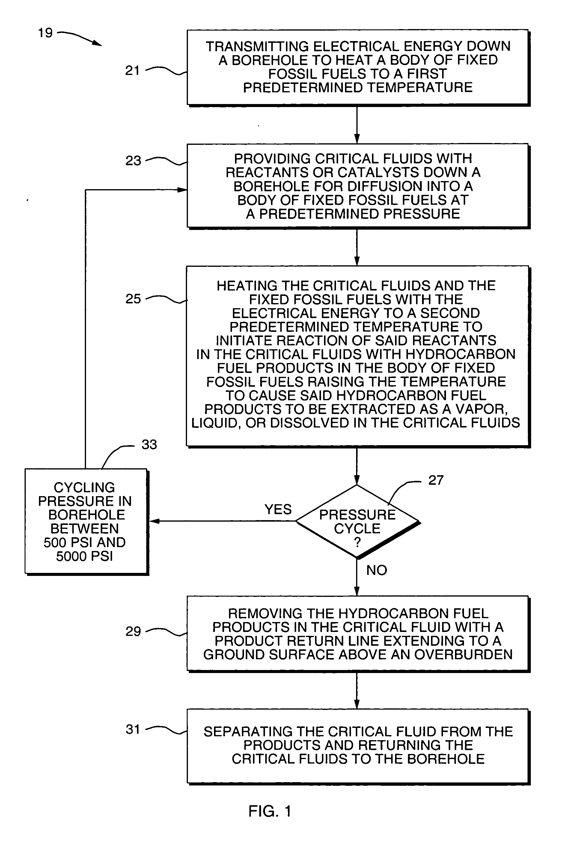
[0019] It is a further object of this invention to provide a method and apparatus for effectively
heating oil shale in situ using a combination of RF energy and a critical fluid.
[0020] It is a further object of this invention to provide a method and apparatus for effectively converting kerogen to useful production in-situ using RF energy and a critical fluid.
[0021] It is a further object of this invention to provide a method and apparatus for effectively obtaining gaseous and liquefied fuels from deep, otherwise uneconomic deposits of fixed fossil fuels using RF energy and critical fluids.
[0027] The RF energy decoupling means comprises an RF
choke connected to a
filter capacitor for each
thermocouple line. Also, the RF energy decoupling means comprises a hollow RF
choke, the RF
choke being formed by the
thermocouple wires which are insulated and rotated to form a coil, each end of the
thermocouple wires being connected to a
filter capacitor. The
wellhead comprises a grounding screen positioned adjacent to an outer surface of the
wellhead forming a
ground plane to eliminate
electromagnetic radiation eminating from around the
wellhead for operator safety and performance. The wellhead comprises a plurality of ground wires extending radially a distance of approximately one
wavelength of the electrical energy frequency and spaced apart at predetermined intervals of approximately 15 degrees. The wellhead comprises a grounding screen positioned adjacent to an outer surface of the wellhead forming a
ground plane, and a plurality of ground wires extending radially from the perimeter of the grounding screen at a distance of approximately one
wavelength of the electrical energy frequency and spaced apart at predetermined intervals. The
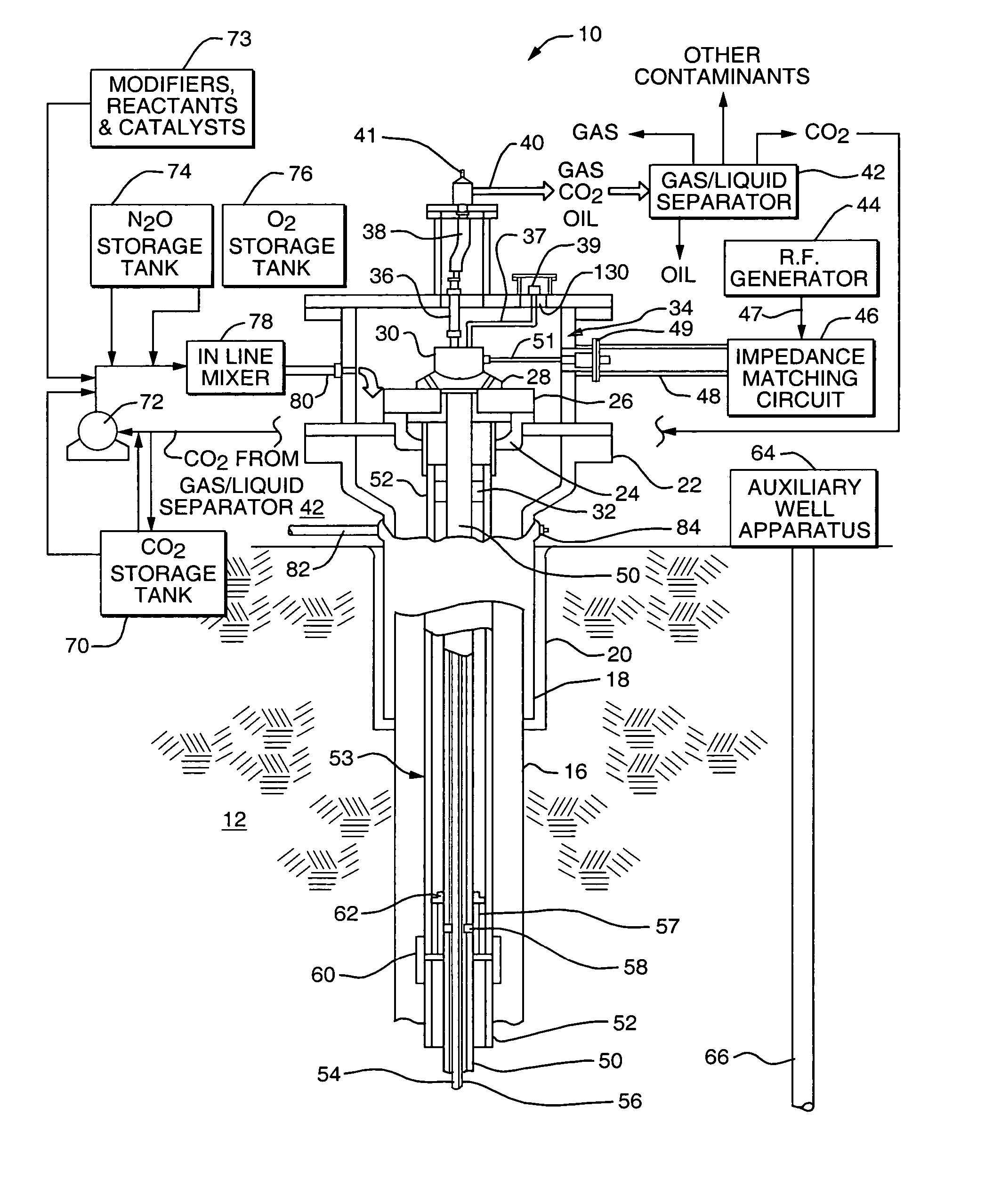
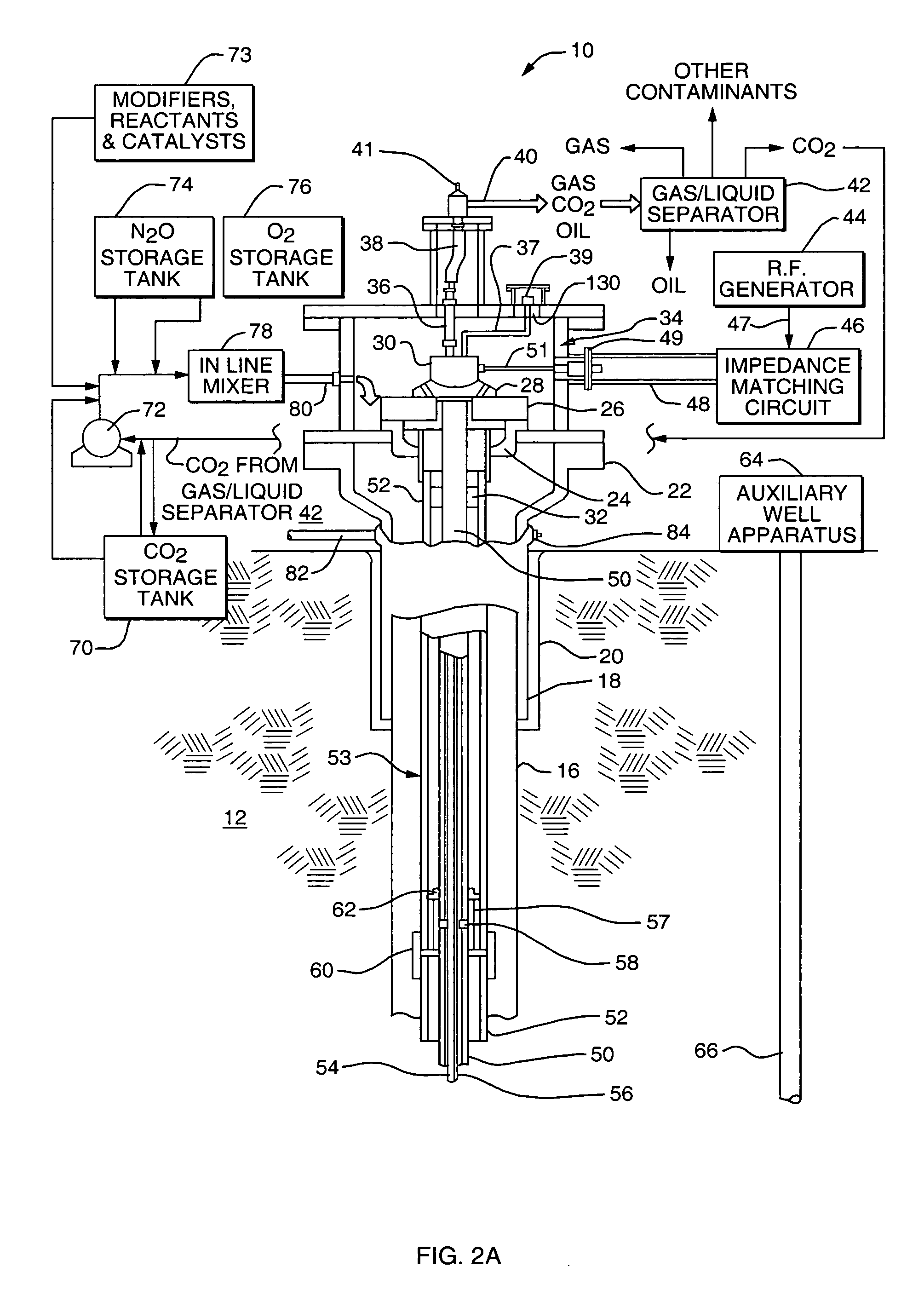
system comprises an auxiliary well spaced apart from the borehole and extending down to the body of fixed fossil fuels for extracting the released hydrocarbon fuels. The auxiliary well comprises an auxiliary wellhead, a well
pipe extending downward from the wellhead, a pump coupled to the auxiliary wellhead for bringing fuel products up to a ground surface above the
overburden, and a gas / liquid separator coupled to the auxiliary wellhead.
[0029] The RF energy decoupling means comprises an RF choke connected to a
filter capacitor for each thermocouple line. Also, the RF energy decoupling means comprises a hollow RF choke, the RF choke being formed by the thermocouple wires which are insulated and rotated to form a coil, each end of the thermocouple wires being connected to a filter
capacitor. Each of the wellheads comprises a grounding screen positioned adjacent to an outer surface of each of the wellheads forming a
ground plane to eliminate
electromagnetic radiation eminating from around the wellhead for operator safety and performance. Each of the wellheads comprises a plurality of ground wires extending radially a distance of approximately one
wavelength of the the electrical energy frequency and spaced apart at predetermined intervals of approximately 15 degrees. Also, each of the wellheads comprises a grounding screen positioned adjacent to an outer surface of the wellhead forming a ground plane, and a plurality of ground wires extending radially from the perimeter of the grounding screen at a distance of approximately one wavelength of the electrical energy frequency and spaced apart at predetermined intervals. The
system comprises an auxiliary well spaced apart from the plurality of boreholes and extending down to the body of fixed fossil fuels for extracting the released hydrocarbon fuels. The auxiliary well comprises an auxiliary wellhead, a well
pipe extending downward from the wellhead, a pump coupled to the auxiliary wellhead for bringing fuel products up to a ground surface above the
overburden, and a gas / liquid separator coupled to the auxiliary wellhead.

