Vehicle air-conditioning system and operation control method therefor

a technology of vehicle air conditioner and operation control method, which is applied in the direction of battery/fuel cell control arrangement, electric devices, propulsion by batteries/cells, etc., can solve the problems of insufficient heating capacity, difficulty in heating, and inability to perform heating by using coolant or combustion exhaust heat, so as to reduce the use of electric heaters, stable heating or dehumidification and heating, the effect of efficient us

Active Publication Date: 2012-08-16
MITSUBISHI HEAVY IND LTD
View PDF6 Cites 97 Cited by
  • Summary
  • Abstract
  • Description
  • Claims
  • Application Information

AI Technical Summary

Benefits of technology

[0052]According to the vehicle air-conditioning system of the present invention, during the heat-pump heating and the dehumidifying and heating, performed by the heat pump cycle, the exhaust heat recovered from the exhaust air from the vehicle interior can be efficiently used as a heat source for heating. Therefore, at a low outside-air temperature or at heating start-up time, it is possible to ensure the required capacity by using the heat of the electric heater to perform stable heating or dehumidifying and heating. Furthermore, when exhaust heat from the motor / battery can be used, or when the vehicle interior temperature reaches a target temperature and exhaust heat from the ventilation-exhaust-heat recovery unit can be used, the exhaust heat is preferentially used to reduce the use of the electric heater as much as possible, thus enabling efficient operation with reduced power consumption and to contribute to extended vehicle travel distance.
[0053]Furthermore, according to the vehicle-air-conditioning-system operation control method of the present invention, based on the predetermined setting values of temperature and pressure, the detected values obtained from sensors provided at predetermined positions for detecting temperature or pressure, and settings of the control panel, it is possible to automatically operate the above-described vehicle air-conditioning system through one of the motor / battery cooling control, which performs refrigerant cooling of the motor / battery; the blowing-mode control, which includes refrigerant cooling of the motor / battery; the heating control; the cooling control; and the dehumidifying and heating control. Therefore, in an electric vehicle, it is possible to realize a comfortable air-conditioning operation by efficiently using exhaust heat and an efficient cooling operation for the motor / battery.

Problems solved by technology

In vehicle air-conditioning systems installed in electric vehicles, since an internal combustion engine is not installed in the vehicles, heating cannot be performed by using coolant or combustion exhaust heat.
The biggest challenge of the heat pump cycle is that heating becomes difficult or the heating capacity becomes insufficient when the outside-air temperature is low or at the operation starting time (heating start-up time), which is well known.

Method used


Image

  • Vehicle air-conditioning system and operation control method therefor
  • Vehicle air-conditioning system and operation control method therefor
  • Vehicle air-conditioning system and operation control method therefor

Examples


first embodiment

[0082]A first embodiment of the present invention will be described below with reference to FIGS. 1 to 27.

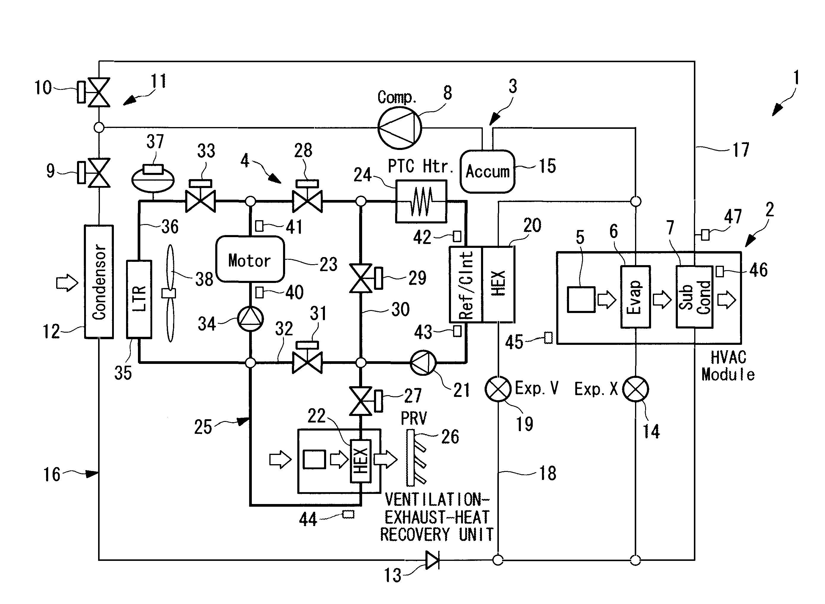
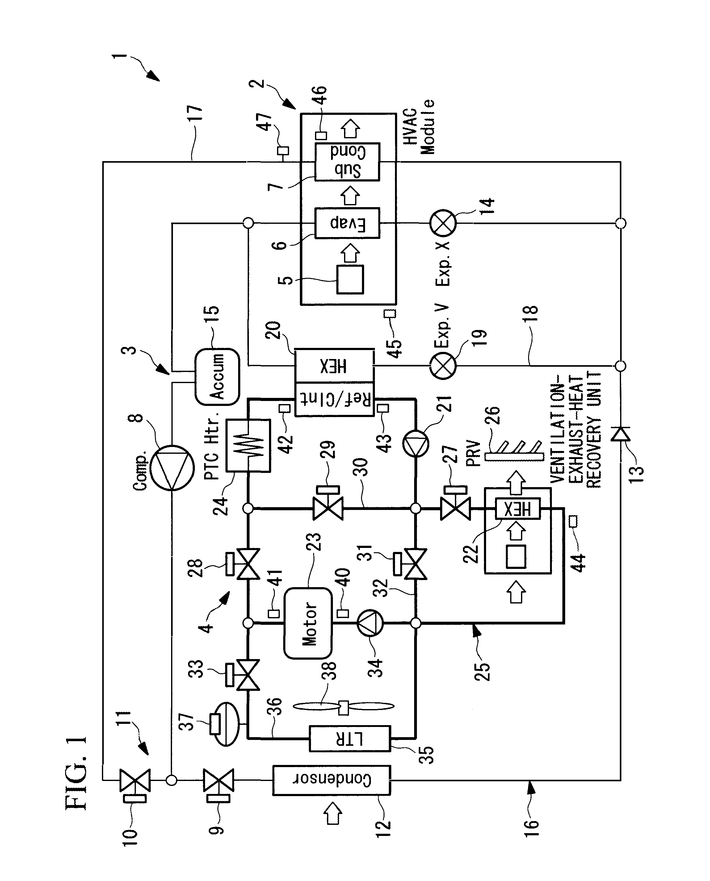
[0083]FIG. 1 is a diagram showing the system configuration of a vehicle air-conditioning system 1 according to the first embodiment of the present invention. The vehicle air-conditioning system 1 is composed of an HVAC (heating ventilation and air conditioning) unit 2, a heat pump cycle 3, and a coolant cycle 4.

[0084]The HVAC unit 2 includes a blower for blowing air (blower) 5, a refrigerant evaporator 6 that constitutes the heat pump cycle 3, and a second refrigerant condenser 7 that is also called a sub-condenser, the refrigerant evaporator 6 and the second refrigerant condenser 7 being sequentially provided in a blowing path of the blower 5 from the upstream side to the downstream side. The HVAC unit 2 is installed in an instrument panel of a vehicle to blow, into a vehicle interior, air whose temperature has been adjusted by the refrigerant evaporator 6 and the second refrig...

second embodiment

[0116]Next, a second embodiment of the present invention will be described with reference to FIGS. 2 to 27.

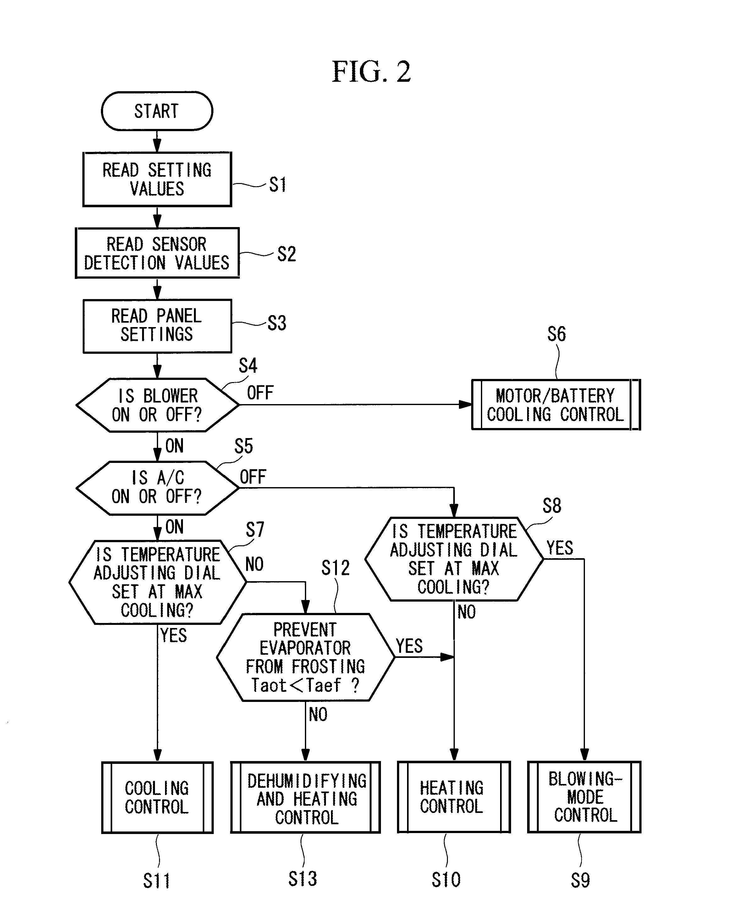
[0117]This embodiment relates to an operation control method for automatically operating the vehicle air-conditioning system of the above-described first embodiment. FIGS. 2 to 7 show control flows of the operation control method. FIG. 8 shows a diagram of a list of operation mode patterns. FIGS. 9 to 27 show cycle diagrams in which the flows of the refrigerant and the coolant are indicated (by arrows in the figures) in respective operation modes.

[0118]According to this embodiment, as shown in FIG. 2, when the operation is started (START), in Step S1, predetermined setting values are read, such as a frost temperature Taef of the refrigerant evaporator 6, an air-cooling switching temperature Tcmi1 of the motor / battery 23, a refrigerant-cooling switching temperature Tcmi2 of the motor / battery 23, a coolant inlet required temperature Tcni1 of the refrigerant / coolant heat exchanger...


PUM


Abstract

A vehicle air-conditioning system includes: an HVAC unit that blows air whose temperature has been adjusted by a refrigerant evaporator and a second refrigerant condenser; a heat pump cycle in which a refrigerant compressor, a refrigerant circuit changeover section, a first refrigerant condenser, a first expansion valve, and the refrigerant evaporator are sequentially connected, in which a second expansion valve and a refrigerant / coolant heat exchanger are connected in parallel with the first expansion valve and the refrigerant evaporator, and in which the second refrigerant condenser is connected in parallel with the first refrigerant condenser; and a coolant cycle in which a coolant circulating pump, a ventilation-exhaust-heat recovery unit, a motor / battery, an electric heater, and the refrigerant / coolant heat exchanger are sequentially connected, and in which the ventilation-exhaust-heat recovery unit, the motor / battery, and the electric heater can be selectively used as a heat source.

Description

TECHNICAL FIELD[0001]The present invention relates to a vehicle air-conditioning system and an operation control method therefor, suitable for use in electric vehicles.BACKGROUND ART[0002]In vehicle air-conditioning systems installed in electric vehicles, since an internal combustion engine is not installed in the vehicles, heating cannot be performed by using coolant or combustion exhaust heat. Thus, in general, a heat pump cycle using an electric compressor is adopted for an electric-vehicle air-conditioning system. The biggest challenge of the heat pump cycle is that heating becomes difficult or the heating capacity becomes insufficient when the outside-air temperature is low or at the operation starting time (heating start-up time), which is well known.[0003]Thus, various improvements have been conventionally proposed. As a heat source for heating, it is conceivable not only to use exhaust heat from a drive motor that includes an inverter and exhaust heat from a battery but also...

Claims


Application Information

Patent Timeline
Patent Type & Authority Applications(United States)
IPC IPC(8): B60H1/22B60H1/32
CPCB60H1/00921B60H1/00392B60H1/20B60L1/003B60L1/02B60L3/0046B60L3/0061B60L11/1803B60L11/1874B60L11/1875B60L2240/34B60L2240/36B60L2240/425B60L2240/545B60L2270/46Y02T10/642Y02T10/7005Y02T10/705B60H1/143B60L50/51B60L58/26B60L58/27B60H1/039Y02T10/64Y02T10/70
Inventor MORISITA, MASATOSISUETAKE, HIDEKIKONDO, TOSHIHISAKATAYAMA, AKIRA
Owner MITSUBISHI HEAVY IND LTD
Why Eureka
Try Eureka