Shelving system

Inactive Publication Date: 2006-03-09
FASTENERS FOR RETAIL
View PDF71 Cites 167 Cited by
  • Summary
  • Abstract
  • Description
  • Claims
  • Application Information

AI Technical Summary

Benefits of technology

[0008] In accordance with one aspect of the present invention, an adjustable length track is provided for a pusher system. The track comprises a first section and a second section operably connected to the first section. A first elongated rail extends longitudinally along the

Problems solved by technology

The nature of the fixed shelves makes it difficult to add and remove products.
Moreover, such shelves make difficult the rotation of the shelved products, which involves moving the older stock to the front of the shelf and positioning new stock behind the older stock.
Also, if merchandise is not displayed at the front of a shelf, it may not catch the shopper's eye, which may cost the merchant sales.
Gravity feeding i

Method used


Image

  • Shelving system
  • Shelving system
  • Shelving system

Examples


first embodiment

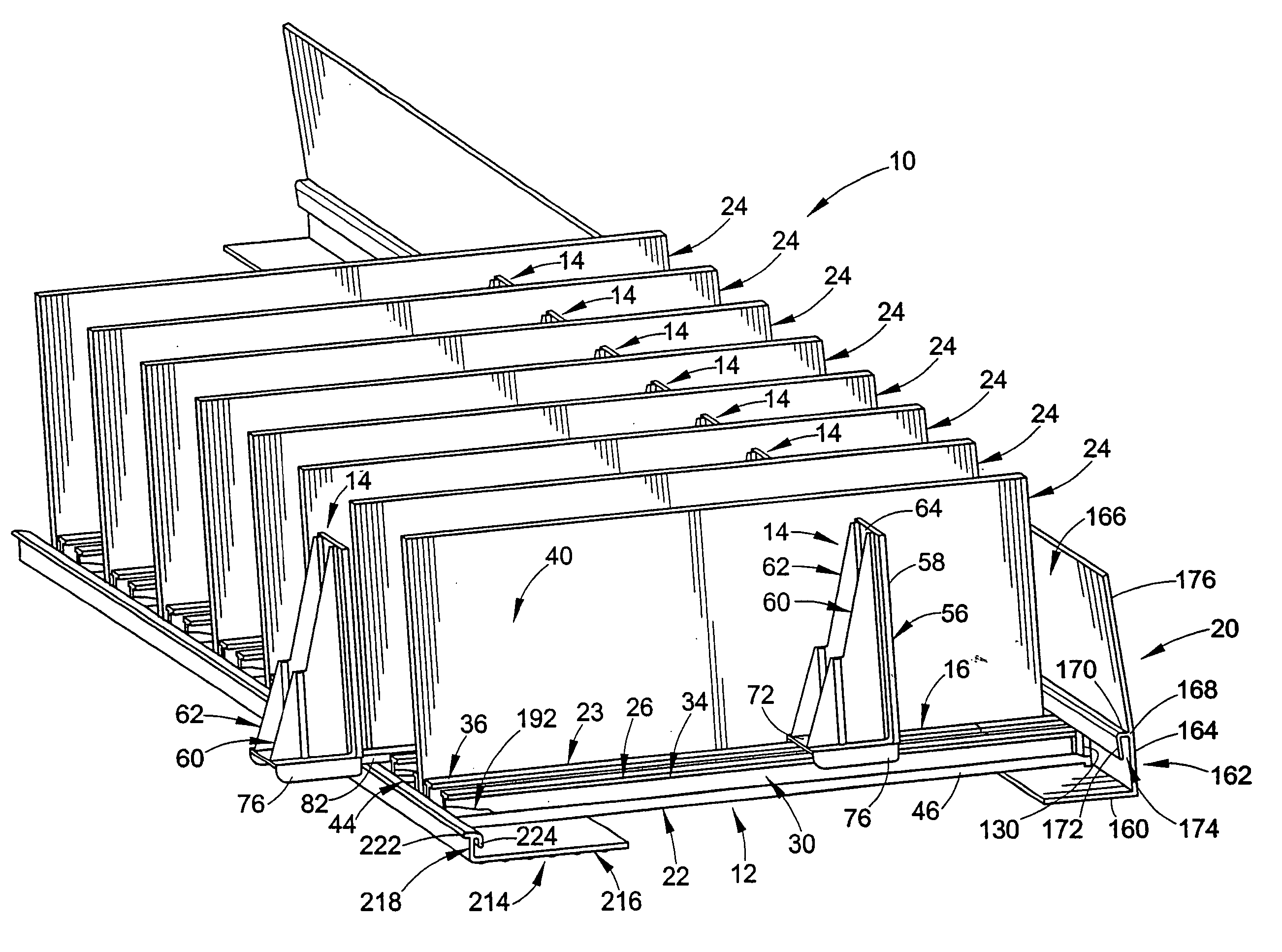
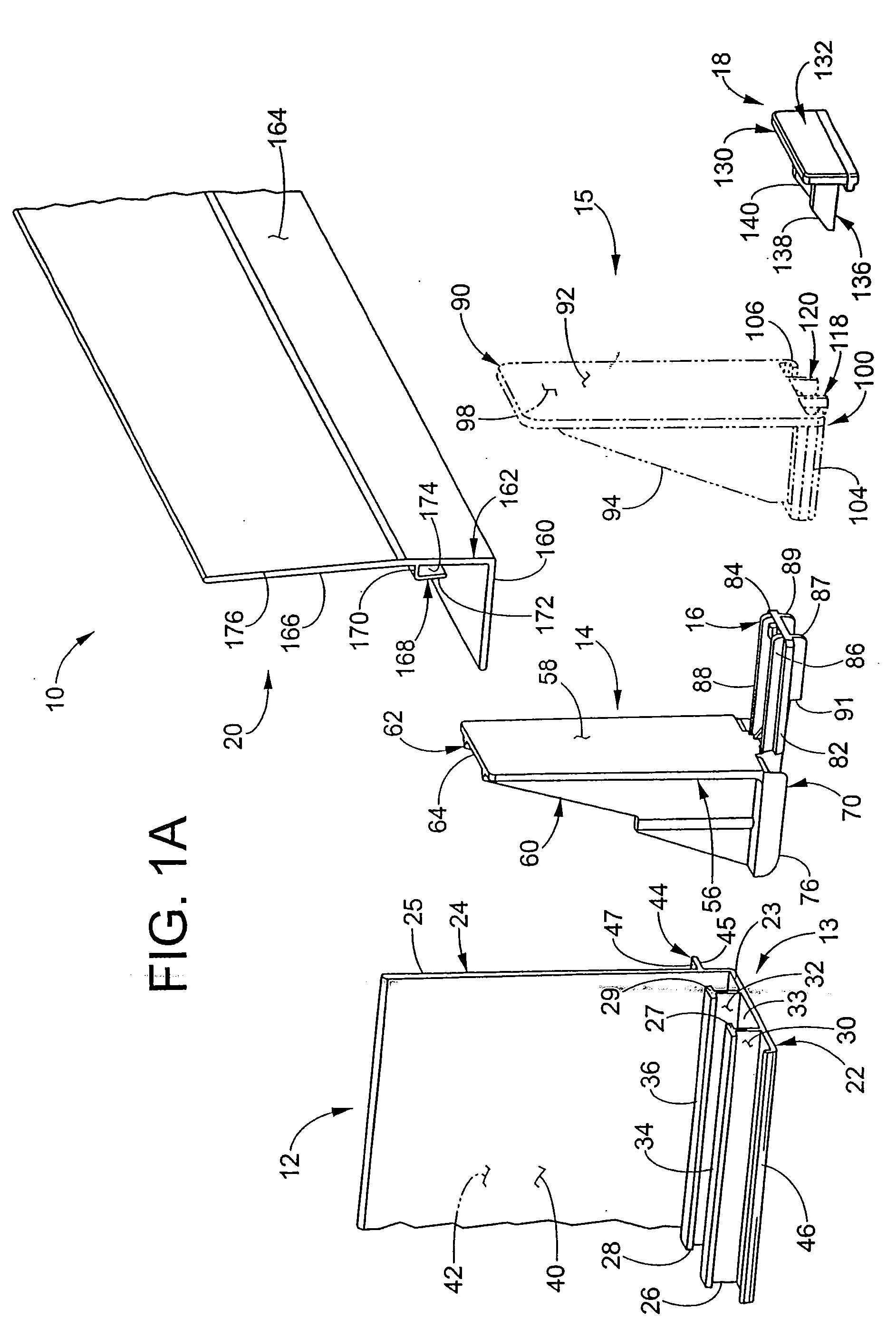
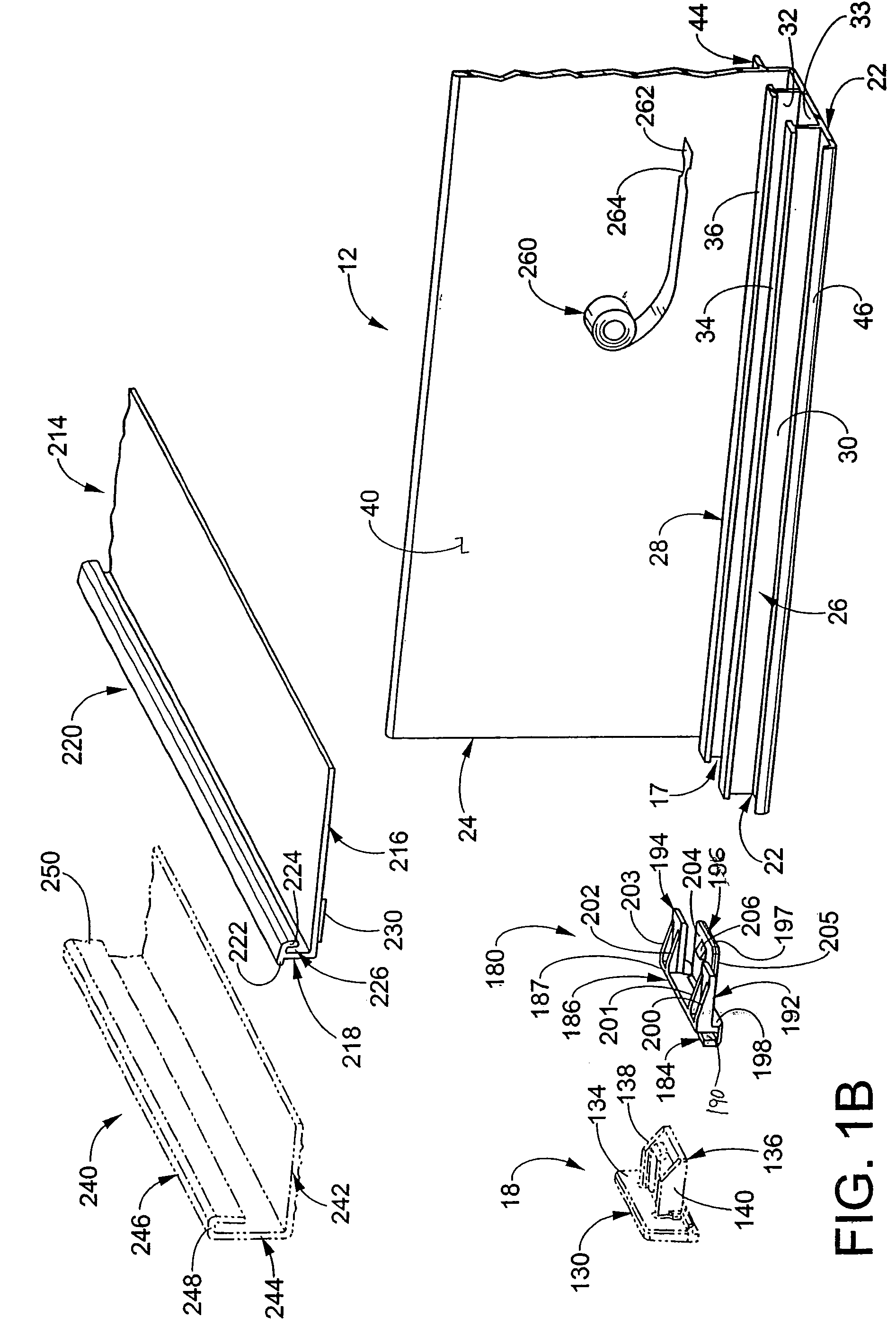
[0041] As shown in FIG. 1A, the paddle 14 includes the foot 16. The paddle 14 further includes a pusher wall 56 with a front face 58 and a pair of gussets 60, 62 which extend rearwardly from a rear face 64. These are generally angled from the top of the pusher wall 56 to a base 70 of the paddle 14. The gussets 60, 62 serve to stiffen the pusher wall 56. The foot 16 extends forward of the pusher wall front face 58. An upper surface (shown in FIG. 2) of the base 70 serves as a spring carrier surface 72. At opposing sides of the spring carrier surface 72 are a pair of outside edges 76 and (not visible) projecting downward generally perpendicular to the spring carrier surface 72. The outside edges are parallel to one another and are spaced to slidably engage, along with an underside or sliding surface 80 of the spring carrier surface 72, the flattened horizontal surfaces 34, 36 of the T-rails 26, 28. The foot 16 extends forwardly transverse to the front face 58 of the pusher wall 56. T...

second embodiment

[0042] As also shown in FIG. 1A, the paddle 15 does not include a foot. However, the paddle 15 does include a pusher wall 90 with a front face 92 and a pair of gussets 94, 96 extending rearwardly from a rear face 98. These generally angle from the top of the pusher wall 90 to a base 100 of the paddle 15. The gussets 94, 96 serve to stiffen the pusher wall 90. An upper surface of the base 100 serves as a spring carrier surface. At opposing sides of the spring carrier surface are a pair of rolled edges 104, 106 projecting downwardly and inwardly. The base 100 also includes a pair of legs 118, 120 extending transverse to a lower or sliding surface 108 of the base 100. The legs 118, 120 are configured to slidably engage the upper surface 33 of the base wall 22 to support and align the paddle 15 along the track 12.

[0043] With continued reference to FIG. 1A, a front end clip 18 for each track 12 is shown. This includes a vertical rectangular front plate 130 with a front face 132 and a rea...


PUM


Abstract

An adjustable length track for a pusher system includes a first section and a second section which is operably connected to the first section. A first elongated rail extends longitudinally along the first section. A second elongated rail extends longitudinally along the second section. The second section is moveable in relation to the first section to allow a length of the track to be changed, thereby enabling the track to be placed on associated shelves of varying depths.

Description

[0001] This application is a continuation-in-part of U.S. patent application Ser. No. 10 / 682,169 which was filed on Oct. 9, 2003 and is still pending. That application is a continuation-in-part of U.S. patent application Ser. No. 10 / 348,306 which was filed on Jan. 21, 2003 and is still pending.FIELD OF THE INVENTION [0002] The present invention generally relates to an adjustable shelving system. More specifically, the present invention relates to an adjustable forward-feeding display shelving system for storing and displaying merchandise of a variety of shapes and sizes and automatically delivering the merchandise to the front of the shelf. The shelving system can be removably attached to an associated shelf and is configured to organize merchandise on the shelf. BACKGROUND OF THE INVENTION [0003] Shelving is used extensively for stocking and storing products or merchandise in a variety of stores. Most stores have immovable shelving which is arranged back-to-back between aisleways. ...

Claims


Application Information

Patent Timeline
IPC IPC(8): A47F1/04A47F1/12
CPCA47F1/126
Inventor MUELLER, PAUL A.KUMP, DANIEL J.
Owner FASTENERS FOR RETAIL
Why Eureka
Try Eureka