Device comprising camera elements

Active Publication Date: 2006-03-16
WSOU INVESTMENTS LLC
View PDF4 Cites 110 Cited by
  • Summary
  • Abstract
  • Description
  • Claims
  • Application Information

AI Technical Summary

Benefits of technology

[0024] Using the present invention can make the selection of the active camera element easier and more intuitive to the user compared to camera selection using e

Problems solved by technology

This can be quite cumbersome and may not be very easy to perform during the call.
Some videotelephony capable phones have only one camera element, which can be mechanically turned in different directions (front and back) but it may not be easy to direct the view of the camera element to the c

Method used


Image

  • Device comprising camera elements
  • Device comprising camera elements
  • Device comprising camera elements

Examples


Example

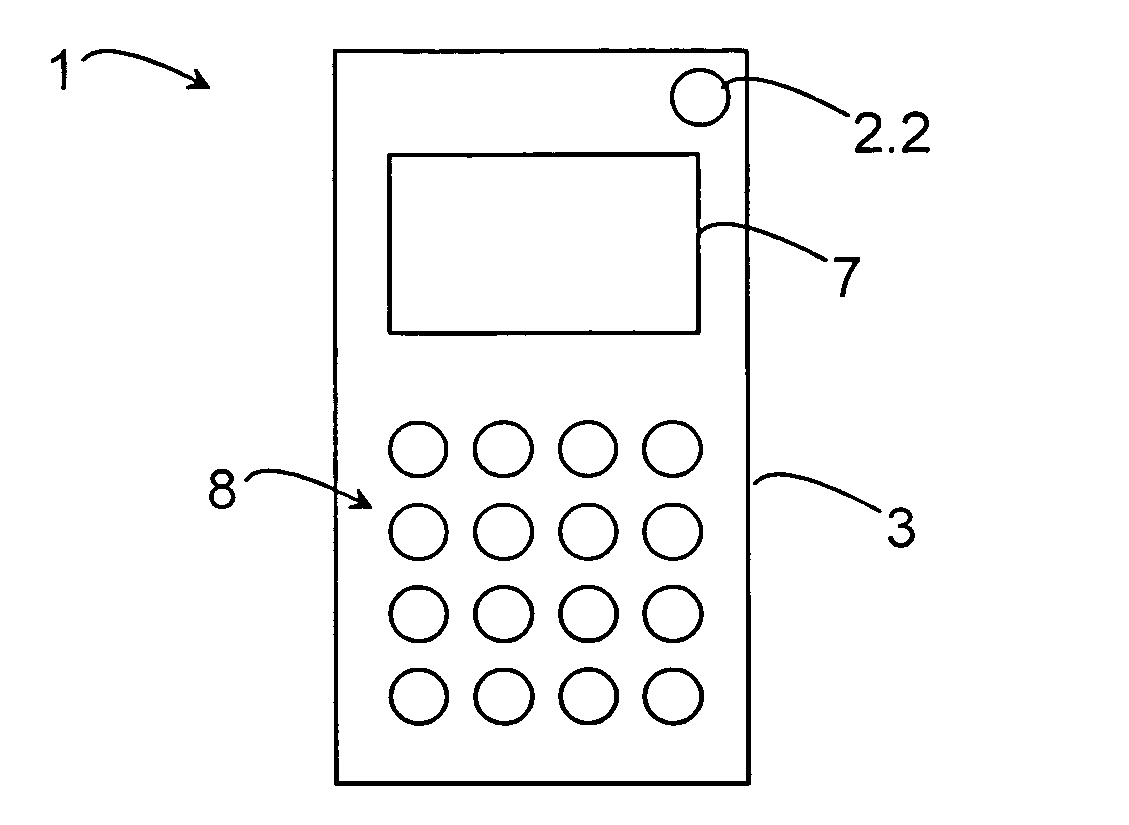
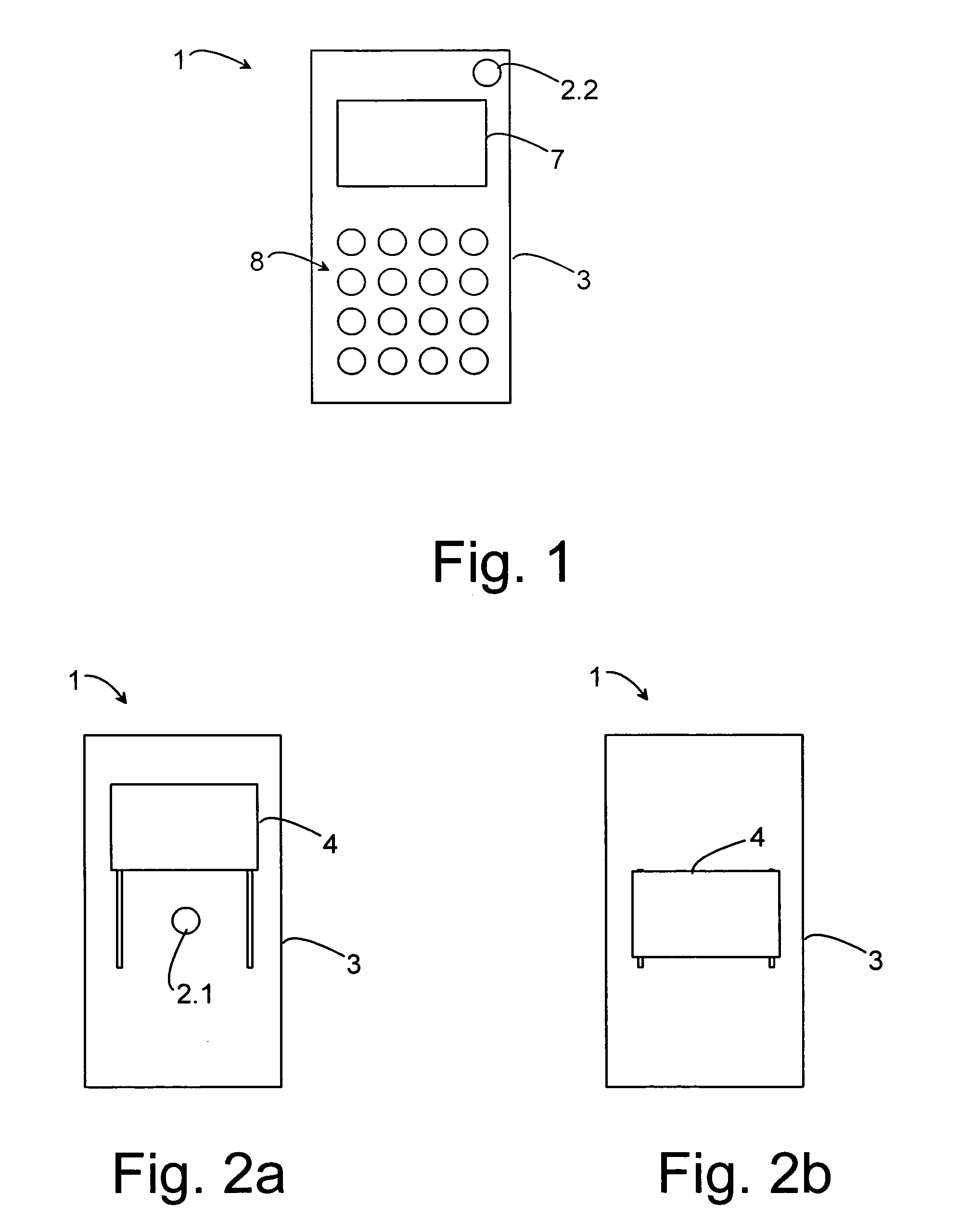
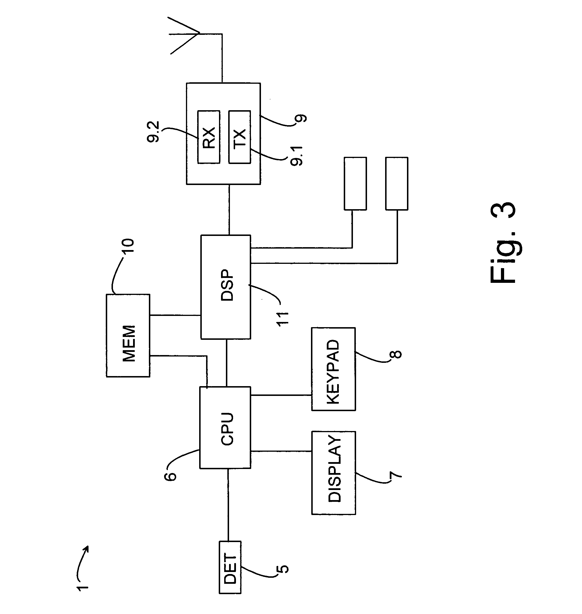
[0030] In the following the invention will be described in more detail with reference to the device 1 of FIGS. 1, 2a and 2b and the block diagram of FIG. 3. The device 1 can be any device with imaging capability. Some non-limiting examples of the device 1 are a mobile communication device such as a mobile phone, a camera, a video camera, a portable computer, a display device, etc. The device 1 has at least a first 2.1 and a second camera element 2.2. The first camera element 2.1 is located, for example, on a first side 3.1 of a housing 3 of the device 1. The second camera element 2.2 is located on another side of the housing 3 of the device, for example on a second side 3.2 which is opposite to the first side 3.1. In this example embodiment the first camera element 2.1 can be protected with a protective cover 4 (FIGS. 2a and 2b). The protective cover 4 is movable between a first position and a second position. In the first position (FIG. 2a) the protective cover 4 is not in front of...


PUM


Abstract

A device comprising a housing; a first camera element located on a first side of the housing for forming image information on a view seen by the first camera element; a second camera element located on a second side of the housing for forming image information on a view seen by the second camera element; an activator for providing a signal from either the first camera element or the second camera element according to a selection, the activator comprising a detector for detecting the selection; and a processing means for processing the obtained image information.

Description

CROSS-REFERENCE TO RELATED APPLICATIONS [0001] This application claims priority under 35 USC §119 to Finnish Patent Application No. 20045342 filed on Sep. 14, 2004. FIELD OF THE INVENTION [0002] The invention relates to a device comprising at least a housing, a first camera element located on a first side of the housing for forming image information on a view seen by the first camera element, and a second camera element located on a second side of the housing for forming image information on a view seen by the second camera element. The invention also relates to a system comprising at least a housing, a first camera element located on a first side of the housing for forming image information on a view seen by the first camera element, and a second camera element located on a second side of the housing for forming image information on a view seen by the second camera element. The invention further relates to a method for controlling operation of a device comprising at least a housing...

Claims


Application Information

Patent Timeline
IPC IPC(8): G03B17/00G03BG03B29/00H04M1/02
CPCG03B29/00H04M1/0235H04M1/0245H04N5/232H04N5/2257H04N5/2258H04N5/2251H04N23/50H04N23/57H04N23/45H04N23/661H04N23/63H04N23/00
Inventor VAPAAKOSKI, SIMO
Owner WSOU INVESTMENTS LLC
Why Eureka
Try Eureka