
Device comprising camera elements

a technology of camera elements and devices, applied in the field of devices comprising camera elements, can solve the problems of not being able to direct the view of the camera element to the correct direction, not being able to perform the correct direction, and not being able to unnecessarily transmit image transmission, etc., to achieve the effect of convenient and intuitive selection of the active camera elemen

Active Publication Date: 2010-03-16
WSOU INVESTMENTS LLC
View PDF12 Cites 7 Cited by
  • Summary
  • Abstract
  • Description
  • Claims
  • Application Information

AI Technical Summary

Benefits of technology

"The present invention relates to a device and method for controlling the handling of images from multiple camera elements. The device includes a detector for detecting the state of a sensing element to select the active camera element. The device can activate either the first or second camera element based on the user's selection. The device also includes an image processor for processing the obtained image information. The invention provides a more intuitive and easy way to select the active camera element compared to traditional camera selection methods. The technical effects of the invention include improved user experience and more efficient camera selection."

Problems solved by technology

This can be quite cumbersome and may not be very easy to perform during the call.
Some videotelephony capable phones have only one camera element, which can be mechanically turned in different directions (front and back) but it may not be easy to direct the view of the camera element to the correct direction.
Therefore, the phone may unnecessarily transmit image transmission during the movement (turning) of the camera element from one direction (e.g. from the view of the face of the user of the phone) to another direction (e.g. to the view which the user of the mobile phone sees).

Method used


Image

  • Device comprising camera elements
  • Device comprising camera elements
  • Device comprising camera elements

Examples


Embodiment Construction

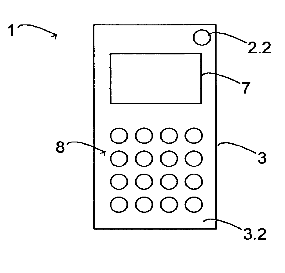
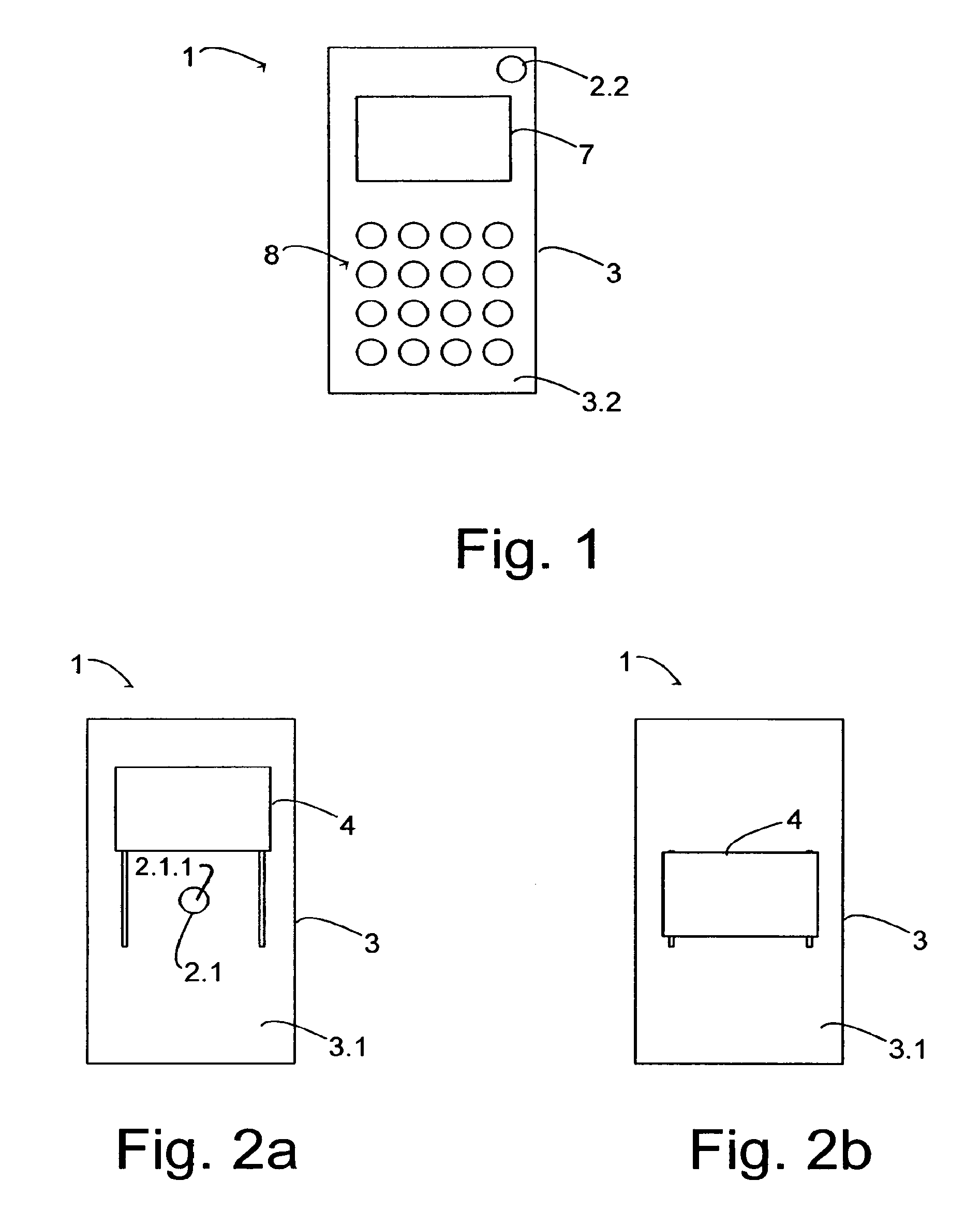
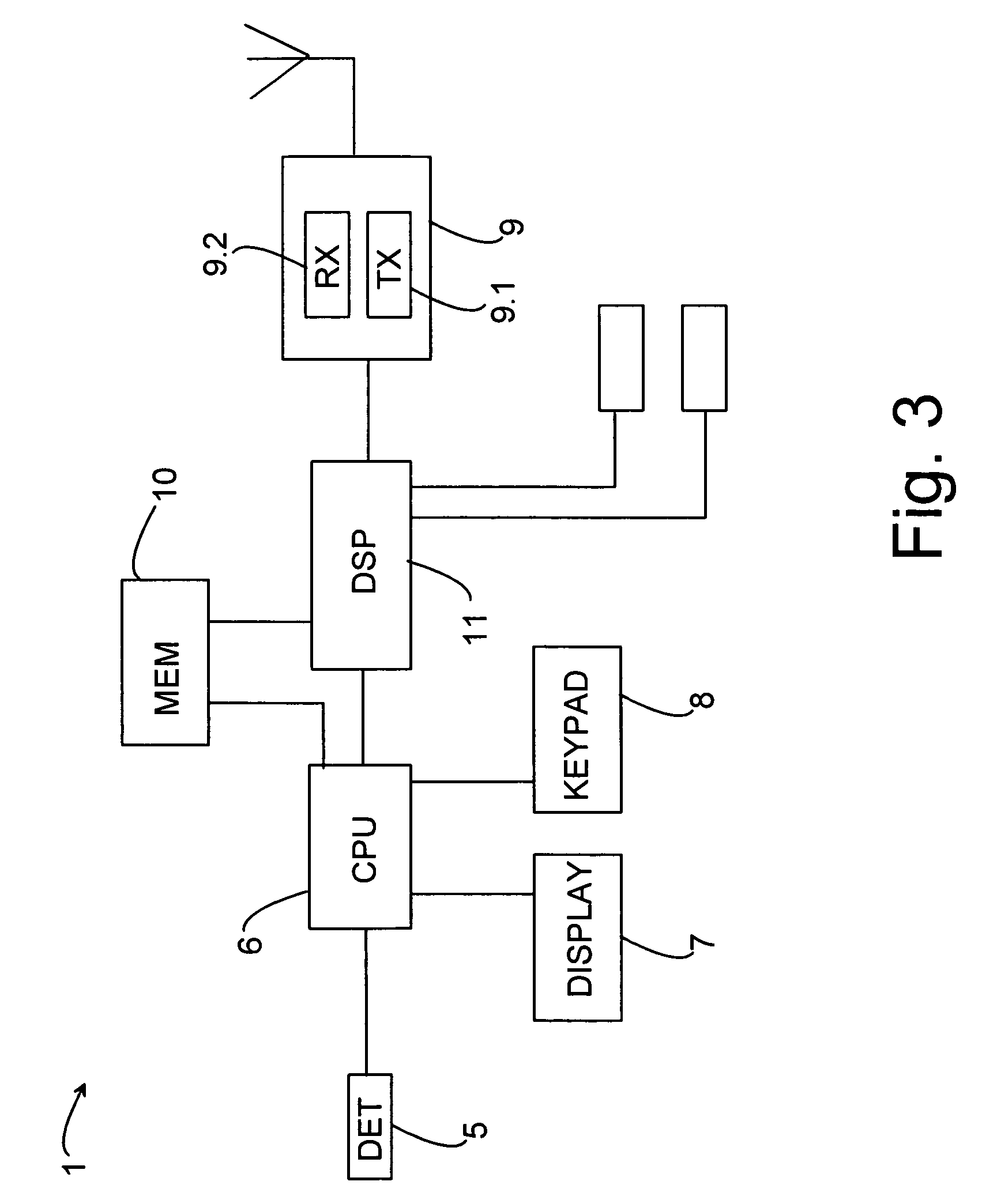
[0031]In the following the method according to an example embodiment will be described in more detail with reference to the state diagram of FIG. 4. First, it is assumed that the selection method is not yet active. This situation is represented by the first state 401 of FIG. 4. The arrow 402 depicts that this mode (Mode=0) will stay as long as the mode is not changed. In this mode the default camera element may be active or none of the camera elements is active. When the method is activated (the mode changes to another mode which is represented in FIG. 4 by Mode=1) the selection signal is examined to determine which camera element 2.1, 2.2 should be activated. The selection signal is formed by the detector 5 to indicate the position of the protective cover 4. The processing element 6 examines the selection signal. If the selection signal indicates that the first camera element 2.1 should be activated (Sel=1) i.e. the protective cover 4 is set to the first position, the state changes...


PUM


Abstract

A device comprising a housing; a first camera element located on a first side of the housing for forming image information on a view seen by the first camera element; a second camera element located on a second side of the housing for forming image information on a view seen by the second camera element; an activator for providing a signal from either the first camera element or the second camera element according to a selection, the activator comprising a detector for detecting the selection; and a processor for processing the obtained image information.

Description

CROSS-REFERENCE TO RELATED APPLICATIONS[0001]This application claims priority under 35 USC §119 to Finnish Patent Application No. 20045342 filed on Sep. 14, 2004.FIELD OF THE INVENTION[0002]The invention relates to a device comprising at least a housing, a first camera element located on a first side of the housing for forming image information on a view seen by the first camera element, and a second camera element located on a second side of the housing for forming image information on a view seen by the second camera element. The invention also relates to a system comprising at least a housing, a first camera element located on a first side of the housing for forming image information on a view seen by the first camera element, and a second camera element located on a second side of the housing for forming image information on a view seen by the second camera element. The invention further relates to a method for controlling operation of a device comprising at least a housing, a f...

Claims


Application Information

Patent Timeline
Patent Type & Authority Patents(United States)
IPC IPC(8): G03B17/00H04N23/00G03BG03B29/00H04M1/02
CPCG03B29/00H04M1/0245H04N5/2251H04N5/2257H04N5/2258H04N5/232H04M1/0235H04N23/50H04N23/57H04N23/45H04N23/661H04N23/63H04N23/00
Inventor VAPAAKOSKI, SIMO
Owner WSOU INVESTMENTS LLC
Learn More