
Interactive tool for inspecting and repairing three dimensional models

Active Publication Date: 2014-09-11
AUTODESK INC
View PDF4 Cites 22 Cited by
  • Summary
  • Abstract
  • Description
  • Claims
  • Application Information

AI Technical Summary

Benefits of technology

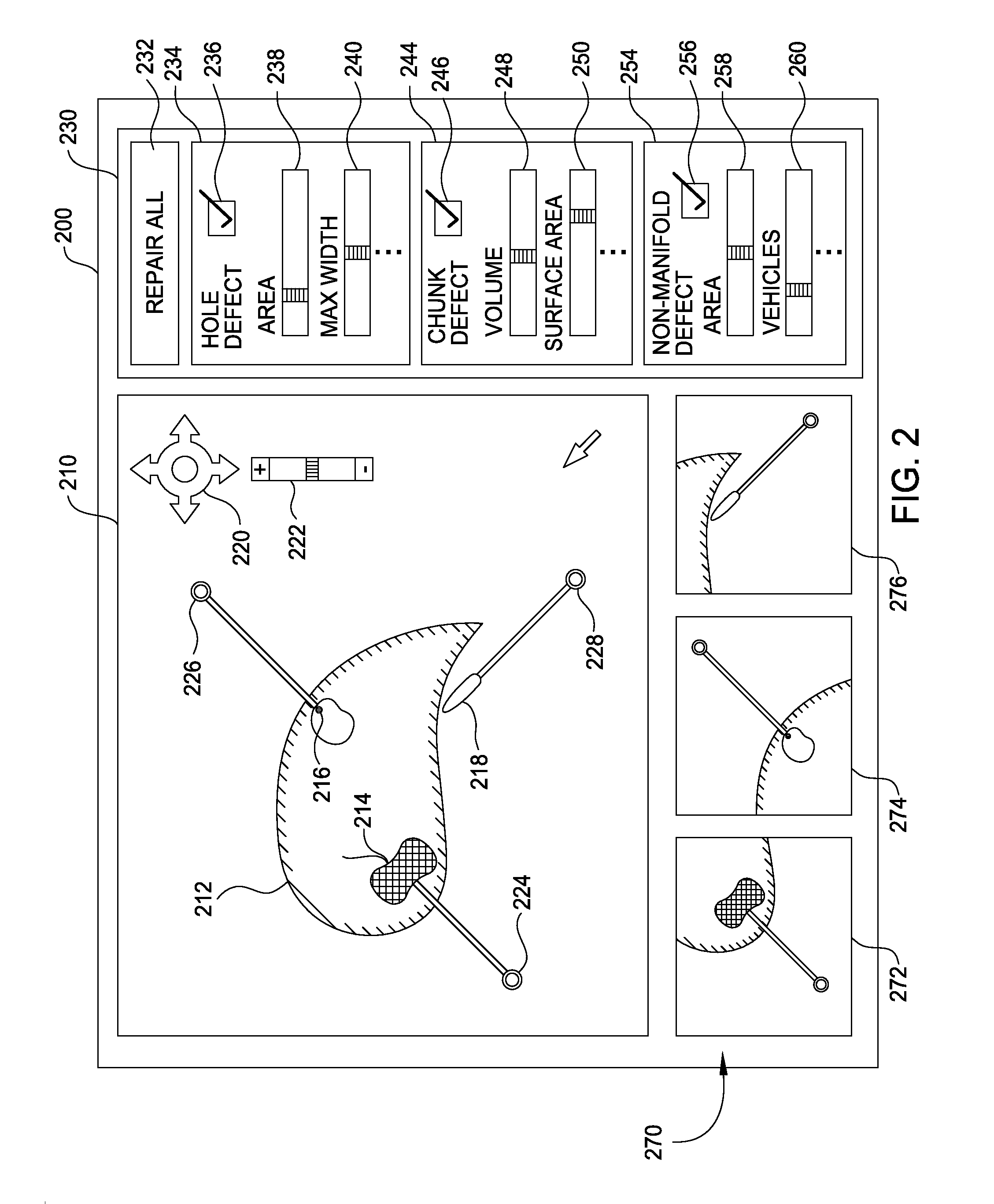
The patent describes a way to repair defects in a computer-generated 3D model. The method involves analyzing the model to identify the defects, creating a visual representation of the model with the defects highlighted, and offering a thumbnail image for each defect to show it from different angles. This makes it easy for users to quickly identify and repair any defects in the model.

Problems solved by technology

The 3D model that represents the object may, in some cases, include various defects where the surface of that model is not properly defined by the rendering application.
The defects mentioned above, as well as other possible types of defects, may be introduced by the rendering application as a consequence of unsuccessful generation of the 3D model.
However, defects in 3D models may have a wide range of sizes, and, in some situations, may be so small relative to the overall size of the 3D model as to be completely invisible to the end-user.
Consequently, the end-user may have significant trouble locating and repairing all defects associated with the 3D model.

Method used


Image

  • Interactive tool for inspecting and repairing three dimensional models
  • Interactive tool for inspecting and repairing three dimensional models
  • Interactive tool for inspecting and repairing three dimensional models

Examples


Embodiment Construction

[0018]In the following description, numerous specific details are set forth to provide a more thorough understanding of the present invention. However, it will be apparent to one of skill in the art that the present invention may be practiced without one or more of these specific details. In other instances, well-known features have not been described in order to avoid obscuring the present invention.

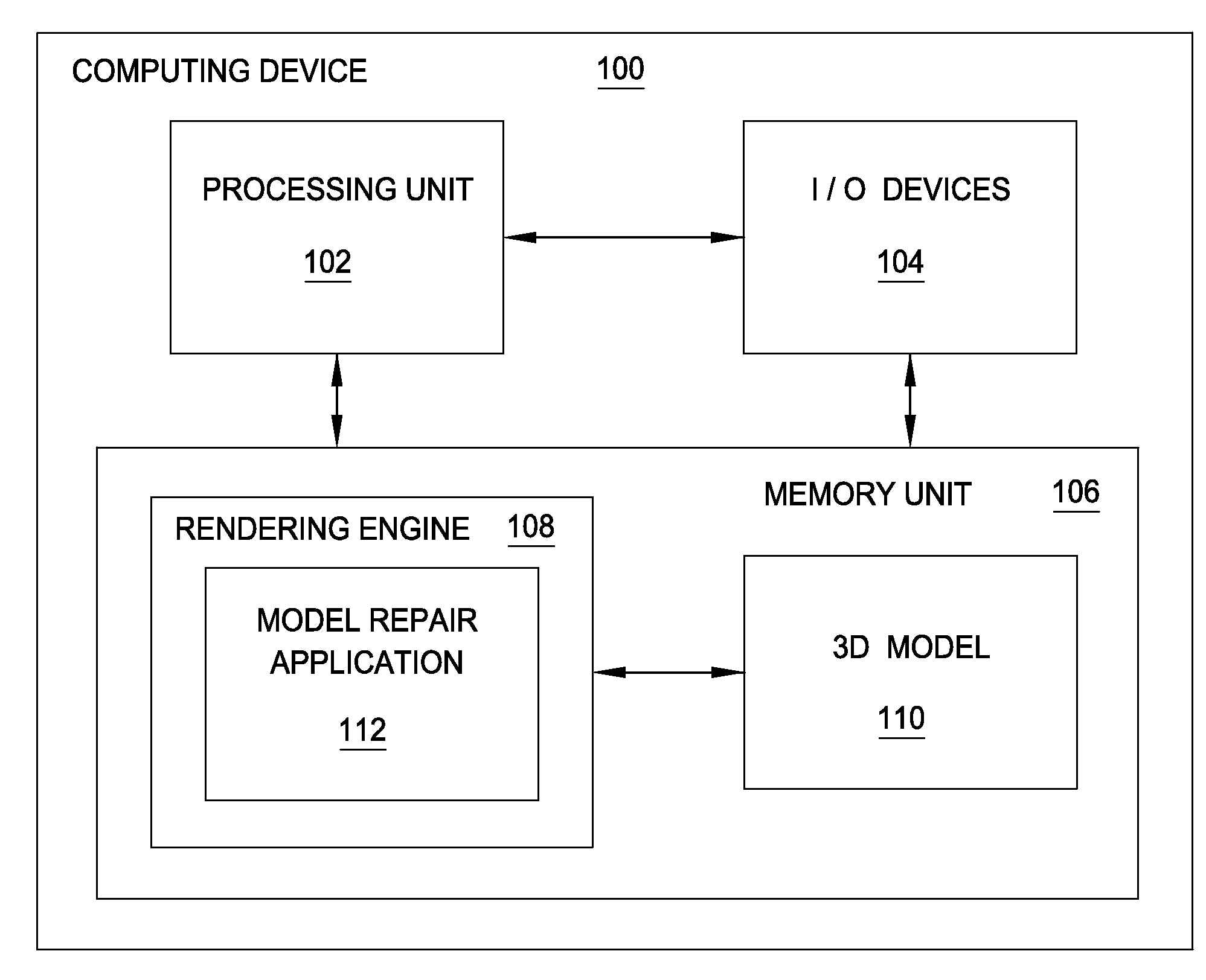
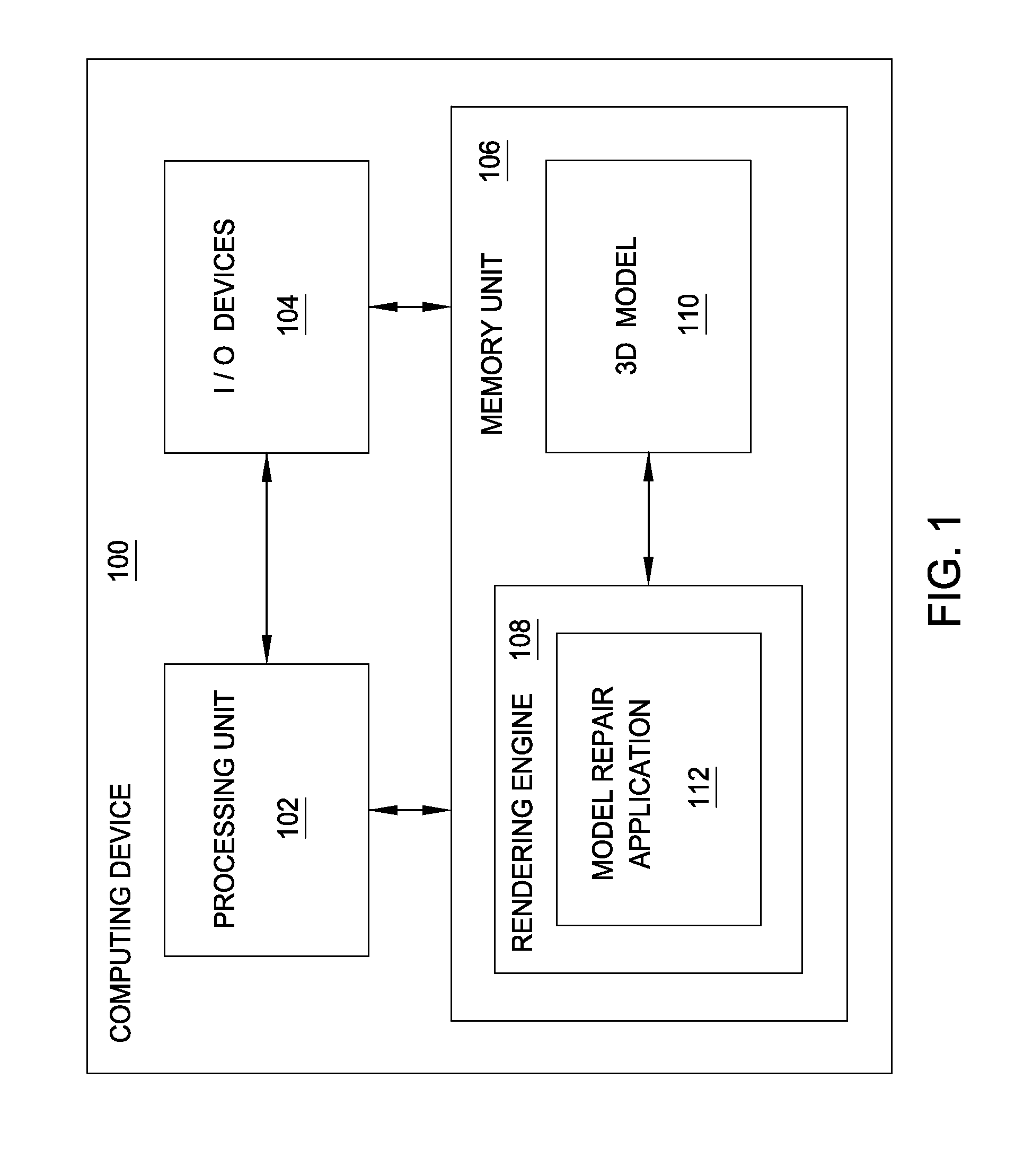
[0019]FIG. 1 illustrates a computing device 100 configured to implement one or more aspects of the present invention. As shown, computing device 100 includes a processing unit 102 coupled to input / output (I / O) devices 104 and to a memory 106. Processing unit 102 may be a central processing unit (CPU), a graphics processing unit (GPU), or a combination of different processing units, such as a CPU configured to operate in conjunction with a GPU. In general, processing unit 102 may be any technically feasible hardware unit capable of processing data and / or executing software applications.

[...


PUM


Abstract

A mesh repair application within a rendering engine is configured to generate a graphical user interface (GUI) that allows an end-user of the rendering engine to inspect and repair various defects associated with a three-dimensional (3D) model. The GUI provides a filmstrip that includes different visual representations of the various defects. When the end-user selects a given representation, the mesh repair application updates the GUI to display a detailed view of the defect associated with the selected visual representation. An advantage of the approach described herein is that the repair of defects associated with the 3D model may be expedited.

Description

BACKGROUND OF THE INVENTION[0001]1. Field of the Invention[0002]The present invention generally relates to computer graphics and, more specifically, to an interactive tool for inspecting and repairing three-dimensional models.[0003]2. Description of the Related Art[0004]A conventional rendering application may be configured to generate a three-dimensional (3D) model that represents the surface of an object within a 3D environment. The object could be, e.g., a real-world object such as a human being, or a virtual object such as a video game character. The 3D model that represents the object may, in some cases, include various defects where the surface of that model is not properly defined by the rendering application. A defect could be, for example, a hole in the 3D model, a detached portion of the 3D model, or a non-manifold region of the 3D model that includes improperly connected vertices and / or edges.[0005]The defects mentioned above, as well as other possible types of defects, m...

Claims


Application Information

Patent Timeline
IPC IPC(8): G06T15/00
CPCG06T15/005G06T19/20G06F3/04815G06F3/04845G06T2200/24G06T2219/2021
Inventor SCHMIDT, RYAN MICHAEL
Owner AUTODESK INC
Learn More