
Detection method of lift guide rail perpendicularity and a detector for implementing this method

a detection method and perpendicularity technology, applied in the direction of mechanical measuring arrangements, lifts, instruments, etc., can solve the problems of low work efficiency and difficulty in achieving automatic data collection

Inactive Publication Date: 2006-03-23
SUN LIXIN +1
View PDF11 Cites 27 Cited by
  • Summary
  • Abstract
  • Description
  • Claims
  • Application Information

AI Technical Summary

Benefits of technology

[0016] The advantages of the present invention are: the detected data are picked up by the sensors and directly inputted into the microprocessor, and analyzed and outputted by the microprocessor, so that automation and intellectualization of perpendicularity detection for lift guide rails are achieved.

Problems solved by technology

The installation quality of the guide rail of a lift, especially the error on perpendicularity, is an important factor affecting the proper operation of the lift.
Its advantages are using simple measuring and metering tools and obtaining results directly from visual measurements but its shortcomings are inconsistent measuring accuracy among different operators with varying operating skill and visual reading errors, the difficulty for achieving automatic data collection, and low work efficiency.

Method used


Image

  • Detection method of lift guide rail perpendicularity and a detector for implementing this method
  • Detection method of lift guide rail perpendicularity and a detector for implementing this method
  • Detection method of lift guide rail perpendicularity and a detector for implementing this method

Examples


embodiment 1

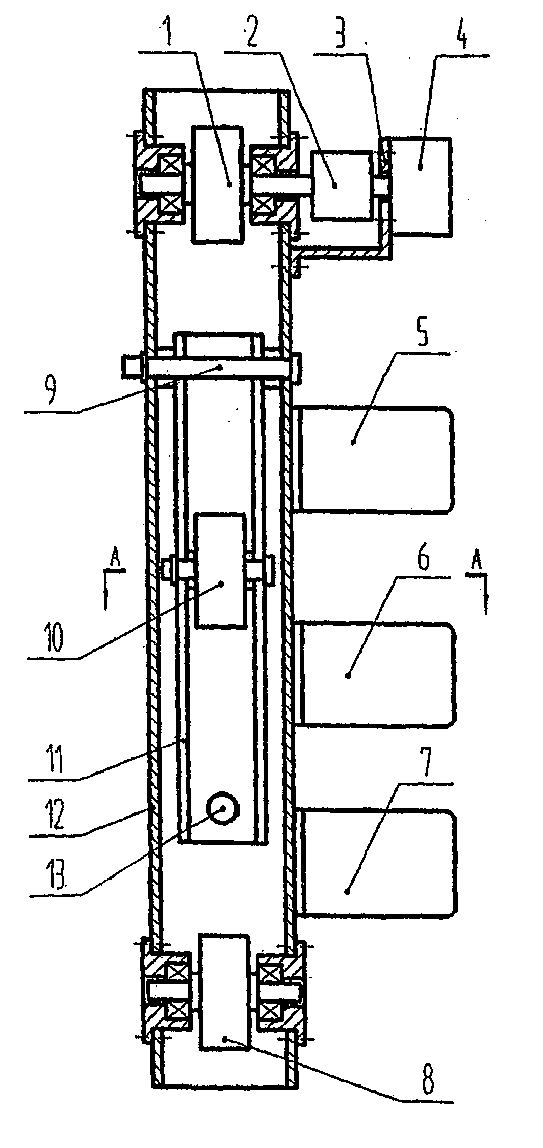
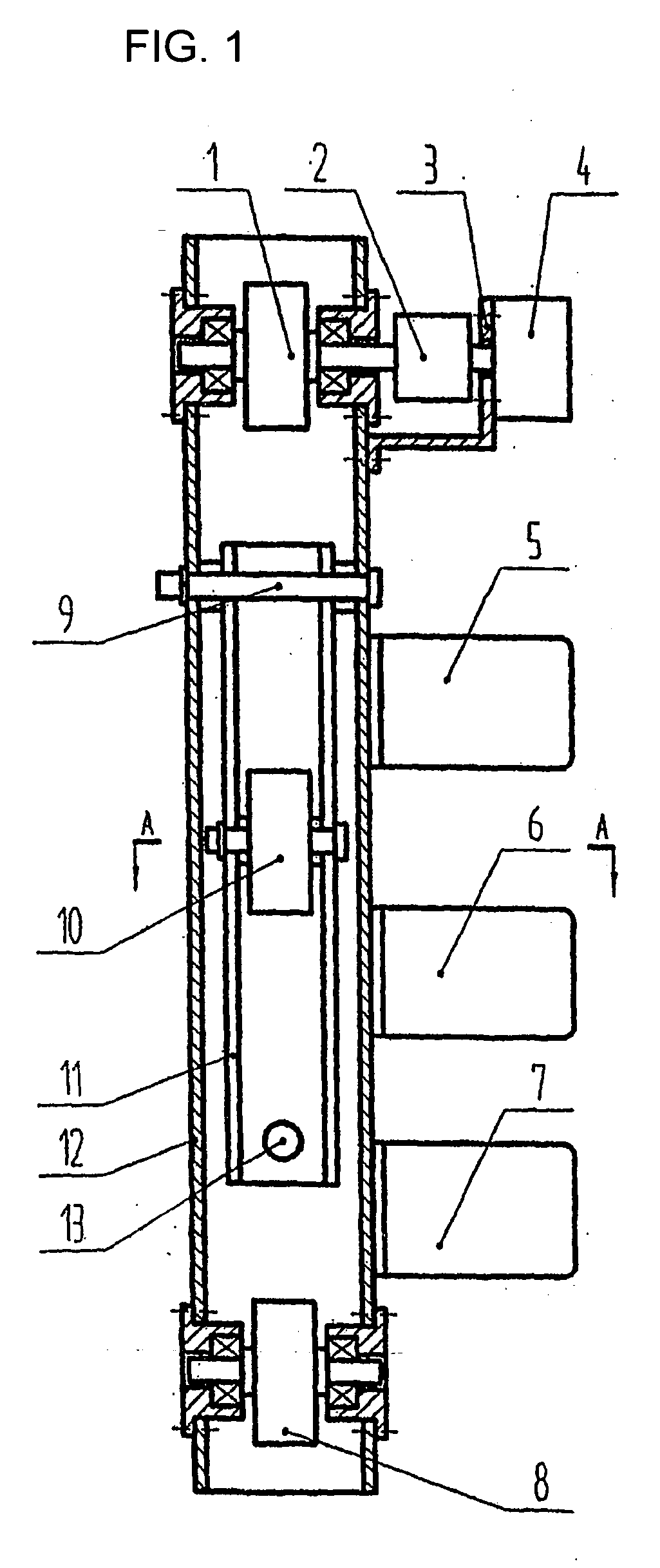
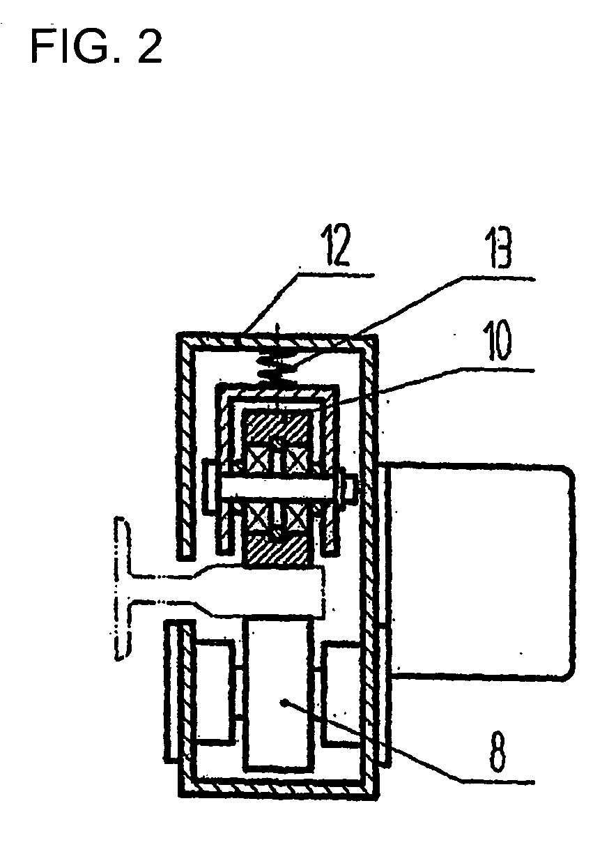
[0022] The detector of this embodiment is mainly used to detect perpendicularity of the side working surface of a lift guide rail. FIG. 1 illustrates the structure of the detector and FIG. 2 shows that the detector heads are contacted tightly with the side working surface by the action of the contact roller at the A-A section.

[0023] In this embodiment, detector heads 1 and 8, installed rigidly on the upper and lower parts of instrument frame 12 respectively, have a roller type structure. For the convenience of measuring and calculation, the predetermined distance between detector head 1 and detector head 8 is 537 mm. In using this detector, detector heads land 8 are contacted tightly with one side working surface of the guide rail and pressing roller 10 contacts tightly with the opposite side working surface of the guide rail, then tightening spring 13 applies a pressure of 20-30N on pressing roller 10 by pressed arm 11 to ensure detector heads 1 and 8 to contact with the side work...

embodiment 2

[0033] The perpendicularity of the side and top working surfaces can be simultaneously detected by the detector of this embodiment. FIG. 3 illustrates the structure of the detector.

[0034] Based on the above description about the operation of embodiment 1 shown in FIG. 1, additional detector heads 14 and 15 are used to detect perpendicularity of top working surface of the guide rail and are installed on the upper and lower parts of instrument frame 12 respectively, outside detector heads 1 and 8. Detector heads 14 and 15 has the structure of a slide block type.

[0035] During the operation, the sliding surfaces of detector heads 14 and 15 contact with the top working surface, the detection method of perpendicularity of the top working surface of the guide rail is the same as that of perpendicularity of the side working surface of the guide rail.

[0036] In embodiment 2, magnets 16 and 17 are installed on detector heads 14 and 15 respectively to press the sliding surfaces of detector h...


PUM


Abstract

A detection method for measuring lift guide rail perpendicularity and an apparatus for practicing the method. The detection method includes the following steps: selecting several monitoring points on a working surface of the lift under testing, measuring seriatim the position coordinates of each monitoring point in the longitudinal direction of the guide rail and the distance between two adjacent monitoring points, measuring seriatim the included angle between the line connecting the two adjacent monitoring points and the plumb line (or the horizontal line), plotting a graphic chart of the perpendicularity error data to obtain the perpendicularity curve for the lift guide rail. The apparatus includes an instrument frame, several detector heads, a displacement sensor, an inclination sensor, a microprocessor and a power supply unit installed on the instrument frame. The advantages of the present invention are: the detected data are picked up directly by the sensors and inputted into the microprocessor, and analyzed and outputted by the microprocessor, so that automation and intellectualization of lift guide rail perpendicularity detection are achieved.

Description

FIELD OF THE INVENTION [0001] The invention relates to a detection method and a detector for implementing the method. Particularly, it relates to a detection method for measuring perpendicularity of the guide rail of a lift and an apparatus for practicing the method. BACKGROUND OF THE INVENTION [0002] The installation quality of the guide rail of a lift, especially the error on perpendicularity, is an important factor affecting the proper operation of the lift. Detection of lift guide rail perpendicularity is a key step to ensure the installation quality of the lift. According to stipulations of GBJ310-88 Detection and Evaluation Standards for Engineering Quality of Lift Installation, the error allowance requirement for lift guide rail perpendicularity is 0.7 mm of per 5 m, using the “plumb line and dipstick metering” method. According to Lift Supervision and Detection Regulations issued by General Administration of Quality Supervision, Inspection and Quarantine of the People's Repu...

Claims


Application Information

Patent Timeline
Patent Type & Authority Applications(United States)
IPC IPC(8): G01C9/06B66B7/12G01C15/00
CPCG01C15/00B66B7/1246
Inventor SUN, LIXINSUN, YAJUAN
Owner SUN LIXIN
Learn More