Autocontrol burner and a combustion control method

a combustion control and burner technology, applied in the direction of burners, combustion regulation, fuel supply regulation, etc., can solve the problems of difficult adjustment of air/oil ratio, low precision, high energy consumption, etc., and achieve low energy consumption, simple mechanical structure, and high efficiency

Inactive Publication Date: 2006-03-30
LI YANXIN
View PDF3 Cites 26 Cited by
  • Summary
  • Abstract
  • Description
  • Claims
  • Application Information

AI Technical Summary

Benefits of technology

[0003] An object of the invention is to provide a combustion control method and an autocontrol burner that can adjust automatically the flow rate of outputting flow rate of the fuel oil by the fuel supplying means and the flow rate of air blown by the air blowing means depending on predetermined air / oil ratio simultaneously and proportionally, without using the damper and the fuel oil regulating valve, so that the objects, i.e., low energy consumption, high efficiency, simple mechanical structure, long lifetime, low noise and high economy environmental index, are attained.

Problems solved by technology

This kind of conventional auto burner has some defects such as high energy consumption (unable to consider both of the air / oil ratios of light oil and heavy oil at the same time, meanwhile difficult to adjust the air / oil ratio and low precision), low efficiency (the motors of the required blower fan and the oil pump are not only large in power, but also always run at the maximum number of revolutions regardless of the flame size), and complicated mechanical structure, short lifetime, great noise and poor economy environmental index etc.

Method used


Image

  • Autocontrol burner and a combustion control method
  • Autocontrol burner and a combustion control method
  • Autocontrol burner and a combustion control method

Examples


Embodiment Construction

[0059] Hereinafter the embodiments of autocontrol burner according to the present invention are described.

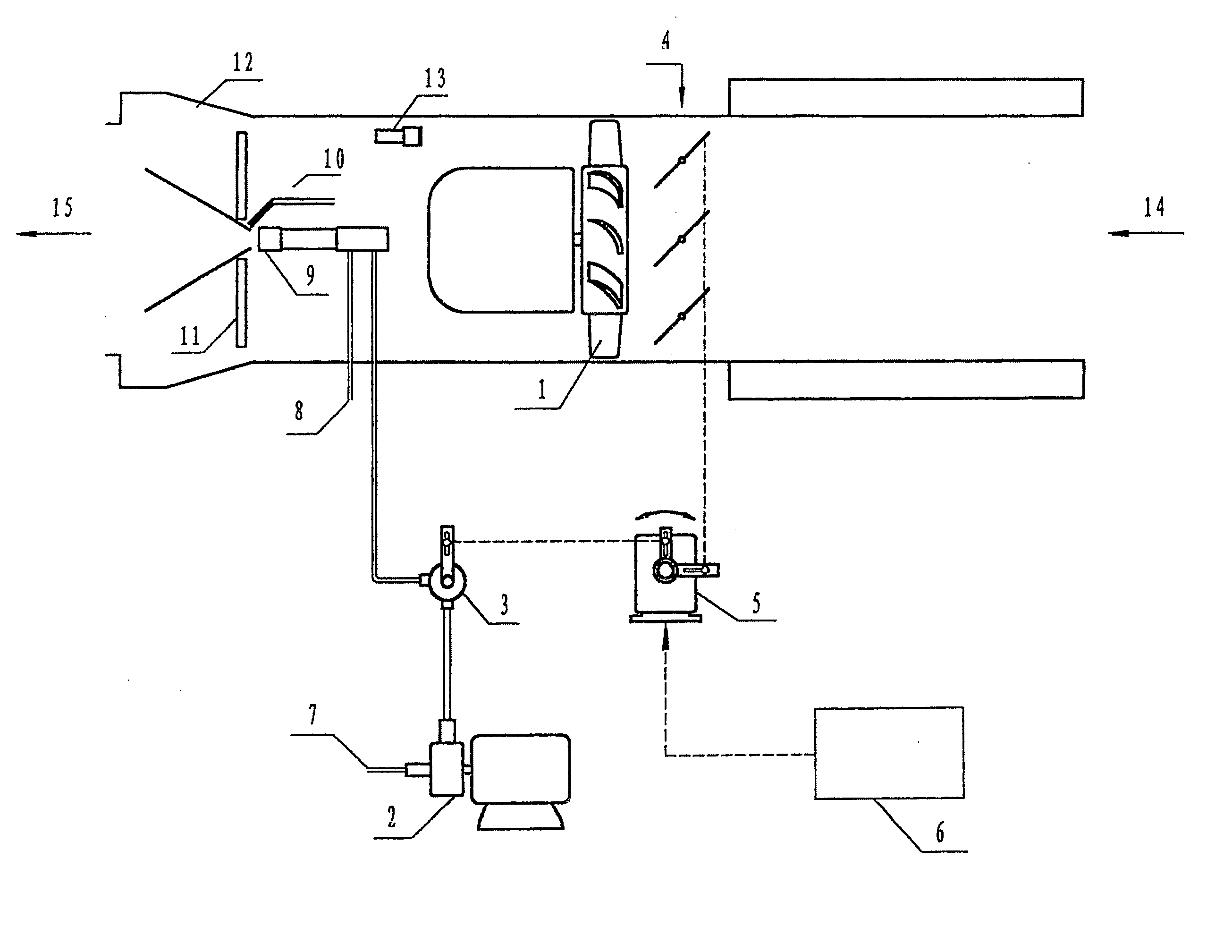
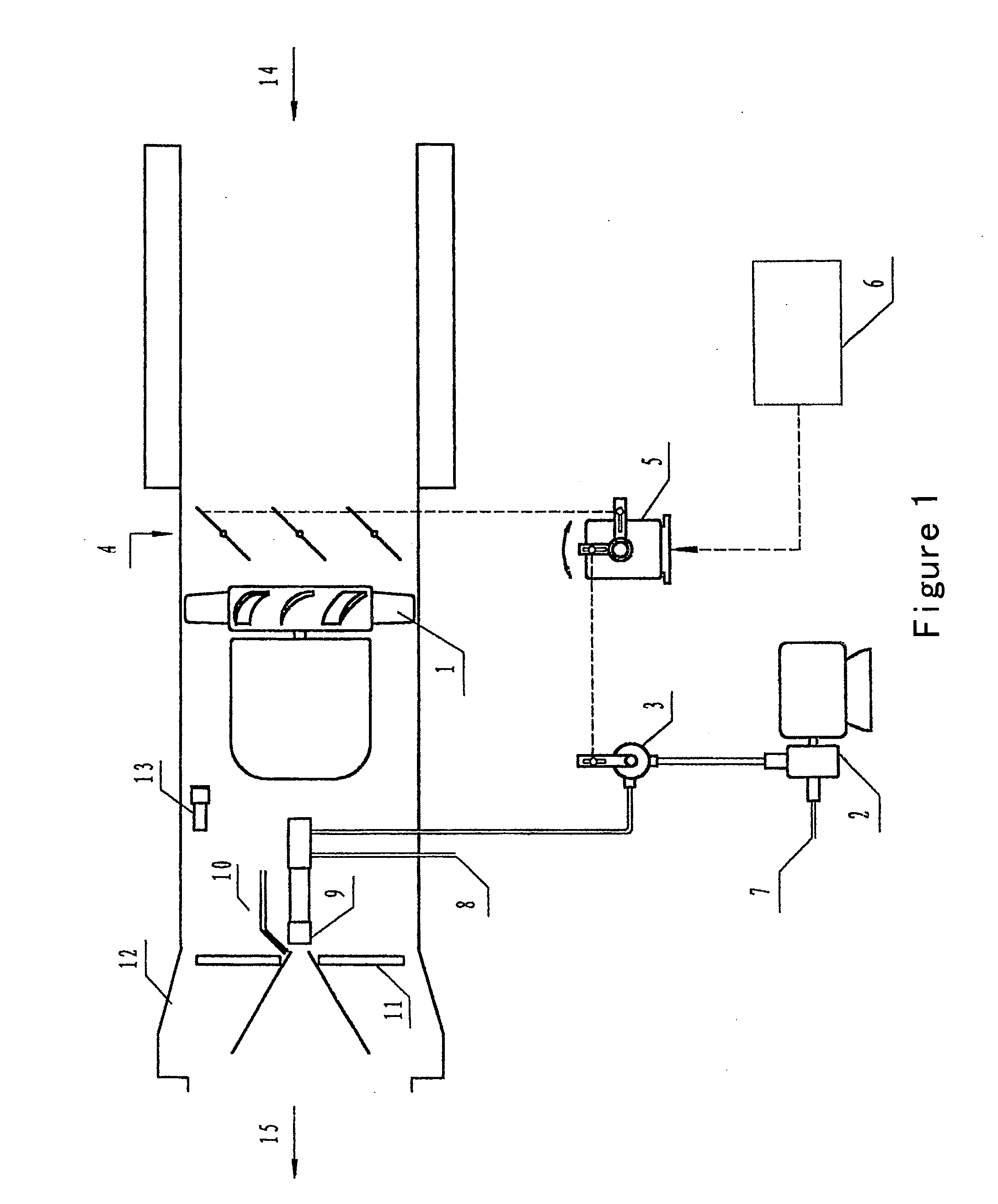
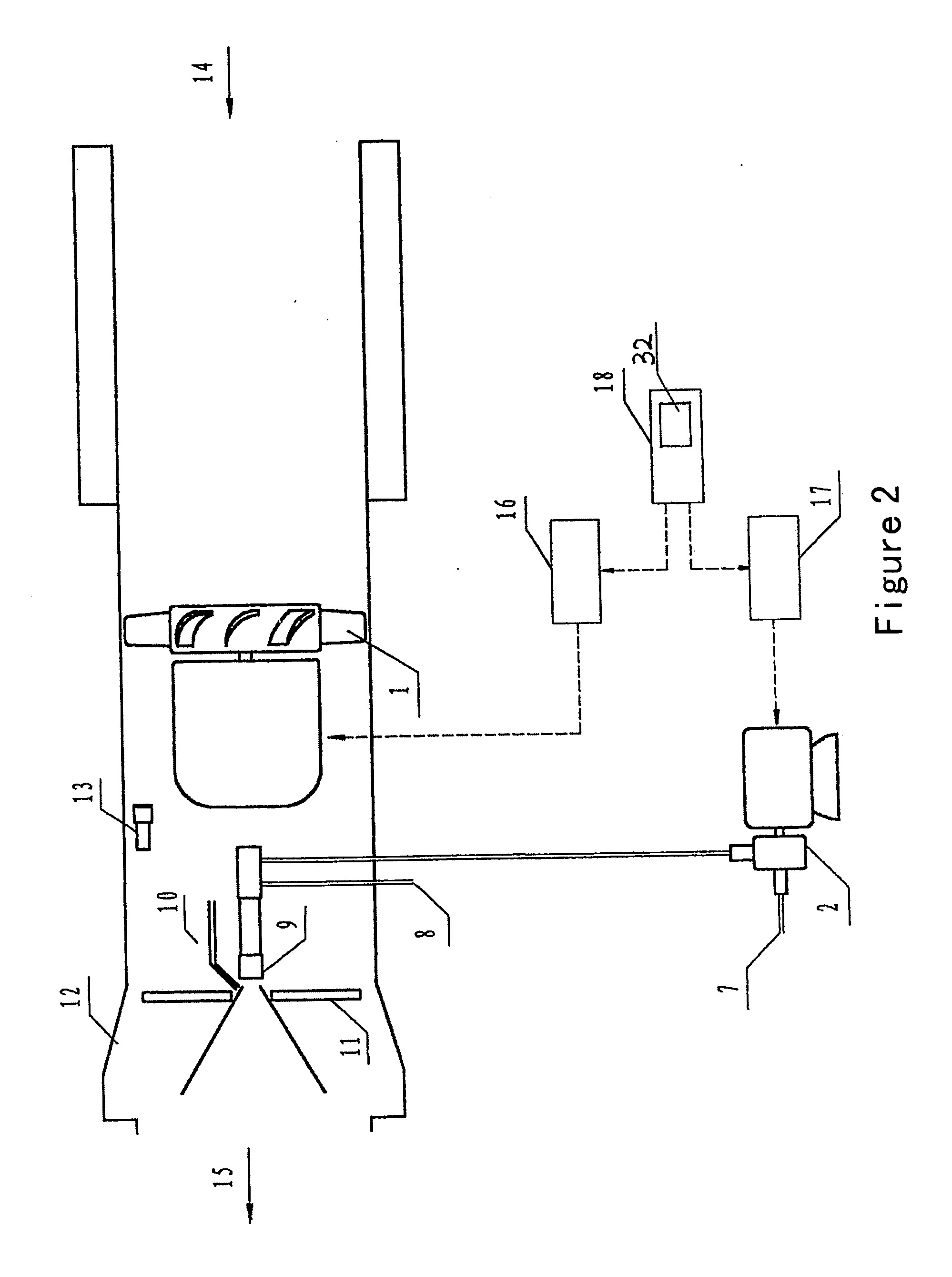
[0060] In FIGS. 2, 3 and 4, an autocontrol burner includes a main body, a gear or a screw type oil pump 2, a blower fan 1, an internal-mixing type pneumatic atomizing spray gun 9 and gas ignition gun 10, and further includes a programmable controller 18, motor speed controllers 16, 17 and signal acquisition assembly such as a flame monitor 13, an oil pressure transmitter 21, an atomized gas pressure switch 25 etc, in which the programmable controller 18 is of Siemens S7 type, the programmable controller 18 may be substituted by an industrial control unit, and the motor speed controllers 16, 17 are respectively of Siemens 430 and Siemens 420 type AC converter, or DC motor governor, or AC motor electromagnetism governor is employed. The oil pump 2 and the blower fan 1 are connected with the programmable controller 18 respectively via motor speed controller 16, 17, and the signal ...


PUM


Abstract

A combustion control method for a burner comprises: the fuel supplying means outputs a given amount of fuel oil to the fuel oil atomizing means; the fuel atomizing means sprays fuel atomized gas; said gas is ignited by the igniter; the amount of air is sent to facilitate burning by the air blowing means; the outputting flow rate of fuel oil and the flow rate of air are adjusted automatically, simultaneously and proportionally by controlling the rotating speed of the electric motors of the fuel supplying means and the air blowing means. An autocontrol burner comprises a main body, an oil pump (2), a blower fan (1), a spray gun (9) and an ignition gun (10), and further comprises a programmable control unit (18), motor speed controller (16,17) and a signal acquisition assembly. The output port of the signal acquisition assembly is connected with the input port of the programmable control unit (18). The oil pump (2) and the blower fan (1) are connected with the programmable control unit (18) by the motor speed controller (16, 17).

Description

FIELD OF THE INVENTION [0001] The present invention relates to adjustment and control of the combustion, particularly to a combustion control method and an autocontrol burner that can adjust automatically the air / oil ratio for the combustion of the fuel oil. BACKGROUND OF THE INVENTION [0002] The present conventional auto burners are all mechanical actuated, i.e. the flame size is adjusted by changing the rotating direction of the motor of the electric actuator, and by means of a connecting rod that actuates a damper and a fuel oil regulating valve. For example, an autocontrol burner is produced by an German company named Benninghoven (see FIG. 1), which can adjust the flame by changing the rotating direction of the motor of the electric actuator 5 using a rotating direction control circuit 6, and by means of the connecting rod that actuates the damper 4 and the fuel oil regulating valve 3. This kind of conventional auto burner has some defects such as high energy consumption (unabl...

Claims


Application Information

Patent Timeline
Patent Type & Authority Applications(United States)
IPC IPC(8): F23N5/00F23N1/02F23D11/00F23D11/26F23N5/08F23N5/18F23N5/24
CPCF23D11/26F23N1/022F23N1/025F23N5/08F23N5/082F23N2039/06F23N2005/185F23N2025/06F23N2033/08F23N2035/06F23N2035/30F23N5/242F23N2225/06F23N2233/08F23N2235/06F23N2235/30F23N2239/06
Inventor LI, YANXIN
Owner LI YANXIN
Why Eureka
Try Eureka