Anchor for hollow walls

a hollow wall and anchoring technology, applied in the field of wall anchors, can solve the problem of somewhat costly design

Active Publication Date: 2006-04-06
COBRA FIXATIONS CIE COBRA
View PDF17 Cites 20 Cited by
  • Summary
  • Abstract
  • Description
  • Claims
  • Application Information

AI Technical Summary

Benefits of technology

[0007] Therefore, in accordance with the present invention, there is provided an anchor for mounting to a hollow wall, comprising a proximal end adapted to be engaged by a rotatable tool to rotate said anchor about a longitudinal axis thereof and to cause it to gradually engage a wall, a distal end adapted to cut through the wall as said anchor is rotated, and a shank between said proximal and distal ends, said shank including at least one expandable leg, said expandable leg being in a collapsed position thereof when said anchor is rotated to mount it to the wall and being located distally past a rear surface of the wall once said anchor is mounted to the wall, said anchor including outer threads, said anchor being adapted to receive therein a threaded fastener and to threadably engage the same distally of said leg such that sufficient rotation of the threaded fastener retracts said distal end towards said proximal end thereby causing said leg to displace to a laterally expanded position thereof.
[0008] Also in accordance with the present invention, there is provided an anchor assembly for mounting to a hollow wall, comprising a threaded fastener and an anchor; said anchor including a proximal end adapted to be engaged by a rotatable tool to rotate said anchor about a longitudinal axis thereof and to cause it to gradually engage a wall, a distal end adapted to cut through the wall as said anchor is rotated, and a shank between said proximal and distal ends, said shank including at least one expandable leg, said expandable leg being in a collapsed position thereof when said anchor is rotated to mount it to the wall and being located distally past a rear surface of the wall once said anchor is mounted to the wall, said anchor including outer threads, said anchor being adapted to receive therein said threaded fastener and to threadably engage the same distally of said leg such that sufficient rotation of said threaded fastener retracts said distal end towards said proximal end thereby causing said leg to displace to a laterally expanded position thereof.
[0009] Further in accordance with the present invention, there is provided an anchor for mounting to a hollow wall, comprising a proximal end adapted to be engaged by a rotatable tool to rotate said anchor about a longitudinal axis thereof and to cause it to gradually engage a wall, a distal end and a shank between said proximal and distal ends, said shank including at least one expandable means, said expandable means being in a collapsed position thereof when said anchor is rotated to mount it to the wall, said anchor including outer threads, said anchor being adapted to receive therein a threaded fastener and to threadably engage the same distally of said expandable means such that sufficient rotation of the threaded fastener retracts said distal end towards said proximal end thereby causing said expandable means to displace to a laterally expanded position thereof behind the wall.

Problems solved by technology

Such designs are somewhat costly, as the anchor requires two distinct components (e.g. the above drilling and toggle members) that also must be assembled together.

Method used


Image

  • Anchor for hollow walls
  • Anchor for hollow walls
  • Anchor for hollow walls

Examples


Embodiment Construction

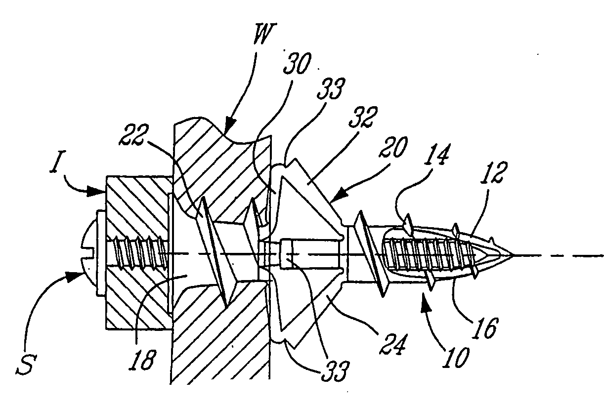
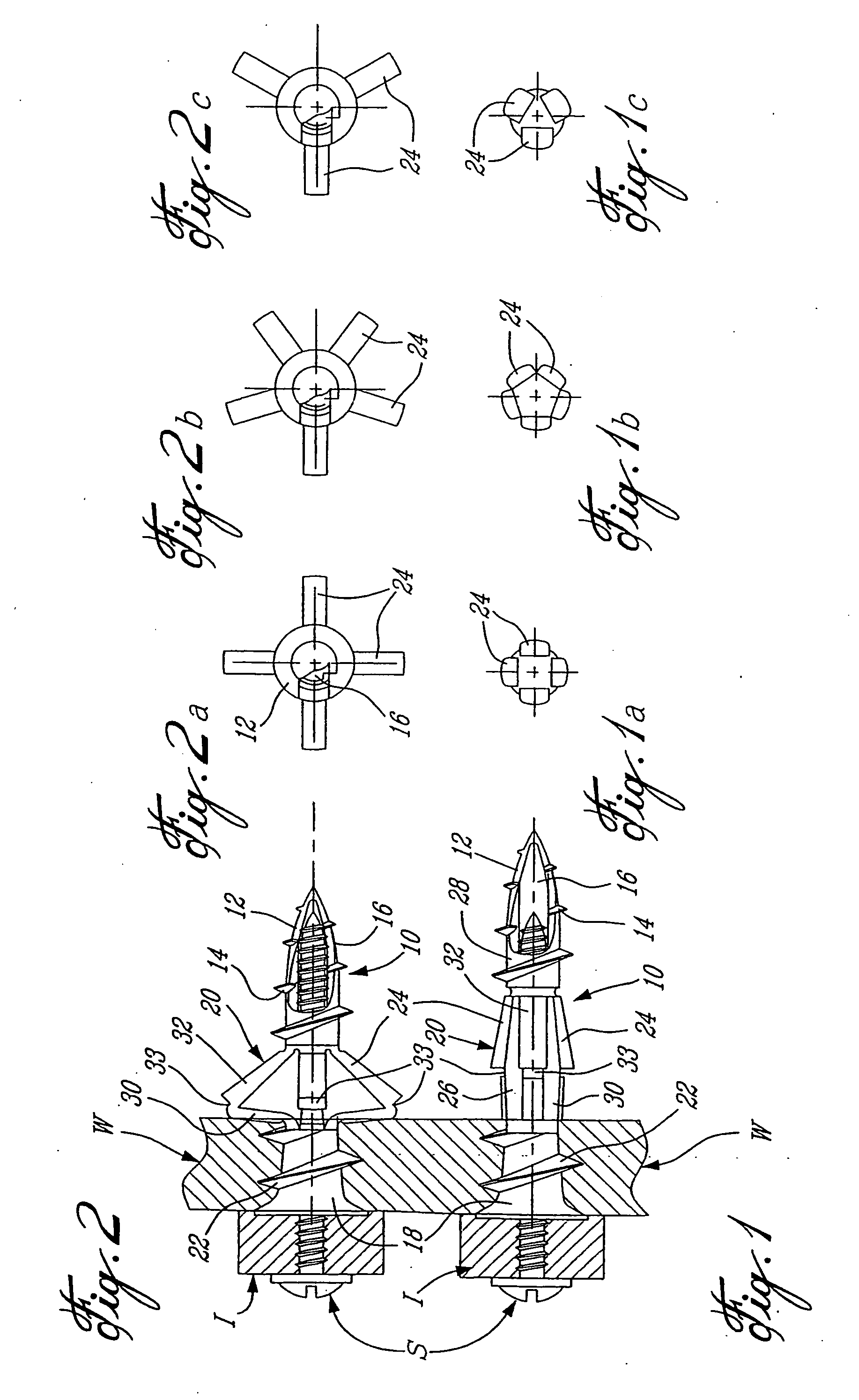
[0053] In accordance with the present invention, FIG. 1 illustrates a wall anchor 10 in its first, i.e. insertion, position, with FIG. 1 showing the wall anchor 10 fully inserted through a wall W and with a screw S engaged in the wall anchor 10 and holding an item I against the wall W. In FIG. 2, the wall anchor 10 is shown in a second, i.e. expanded, position thereof wherein the wall anchor 10 is further secured to the wall W, as explained in details hereinafter. The wall anchors described herein are generally all made of plastics material, e.g. nylon.

[0054] The wall anchor 10 is hollow, for receiving the screw S therein, and comprises a pointed distal tip 12 provided with a partial thread 14 therearound and defining an opening 16. Proximally, the wall anchor 10 includes a head 18 and, between the head 18 and the distal tip 12, the wall anchor 10 comprises a shank 20. The proximal portion of the shank 20 includes a thread 22 and, between the threads 14 and 22, the shank 20 include...


PUM


Abstract

An anchor (910) for mounting to a hollow wall (W) made of friable material comprises a proximal flanged end (918) adapted to be engaged by a rotatable tool (B) to rotate the anchor (910) about a longitudinal axis (A) thereof and to cause is to gradually engage the wall (W). The anchor (910) also includes a distal end (912) adapted to cut through the wall (W) as the anchor (910) is rotated, and a shank (920) extending between the proximal and distal ends (918, 912). The shank (920) includes at least one expandable leg (924) that is in a collapsed position thereof when the anchor (910) is rotated to mount it to the wall (W) and that is located distally beyond a non visible surface of the wall (W) once the anchor (910) has been mounted to the wall and is in a first position thereof. The wall anchor (910) includes an outer thread (922) that securely engages the wall (W). A threaded fastener (B), e.g. a screw, is adapted to be introduced in the anchor (910) and to threadably engage the same distally of the leg (924) such that sufficient rotation of the threaded fastener (B) retracts the distal end (912) towards the proximal end (918) thereby causing the leg (924) to displace to a laterally expanded position thereof and to engage the non visible surface of the wall (W).

Description

BACKGROUND OF THE INVENTION [0001] 1. Field of the Invention [0002] The present invention relates to wall anchors and, more particularly, to self-drilling anchors for use typically in hollow walls made of friable materials, e.g. plasterboard, gypsum, etc. [0003] 2. Description of the Prior Art [0004] The Ernst et al, Gianuzzi and McSherry U.S. Pat. Nos. 4,601,625, 5,234,299 and 5,529,449, respectively, each disclose an anchor which is turned in a wall made of friable material and is retained in the wall by virtue of the friable material being compressed between the root and deep thread spiraled along the cylindrical body of the anchor and between the proximal end of the thread and flanged end of the anchor which becomes embedded in the front surface of the wall. A work piece is then fastened to the wall by a screw fastener that is screwed into the visible open end of the anchor and holds the workpiece between the flanged end of the anchor and the head of the screw fastener. [0005] T...

Claims


Application Information

Patent Timeline
Patent Type & Authority Applications(United States)
IPC IPC(8): F16B13/04F16B13/00F16B13/06
CPCF16B13/002F16B13/061
Inventor MCDUFF, PIERRELABELLE, RICHARDCROSSLEY, WILLIAMANGUYEN, LANGVILLAGRASA, MICHELBOUCHARD, ANDRE
Owner COBRA FIXATIONS CIE COBRA
Why Eureka
Try Eureka