Pneumatic tire

Inactive Publication Date: 2006-04-20
YOKOHAMA RUBBER CO LTD
View PDF3 Cites 3 Cited by
  • Summary
  • Abstract
  • Description
  • Claims
  • Application Information

AI Technical Summary

Benefits of technology

[0007] It is an object of the present invention to provide a pneumatic tire having better traction performance and that is resistant to center-wear.

Problems solved by technology

However, the conventional pneumatic tire undergoes irregular wear, particularly on unpaved roads.

Method used


Image

  • Pneumatic tire
  • Pneumatic tire
  • Pneumatic tire

Examples


Embodiment Construction

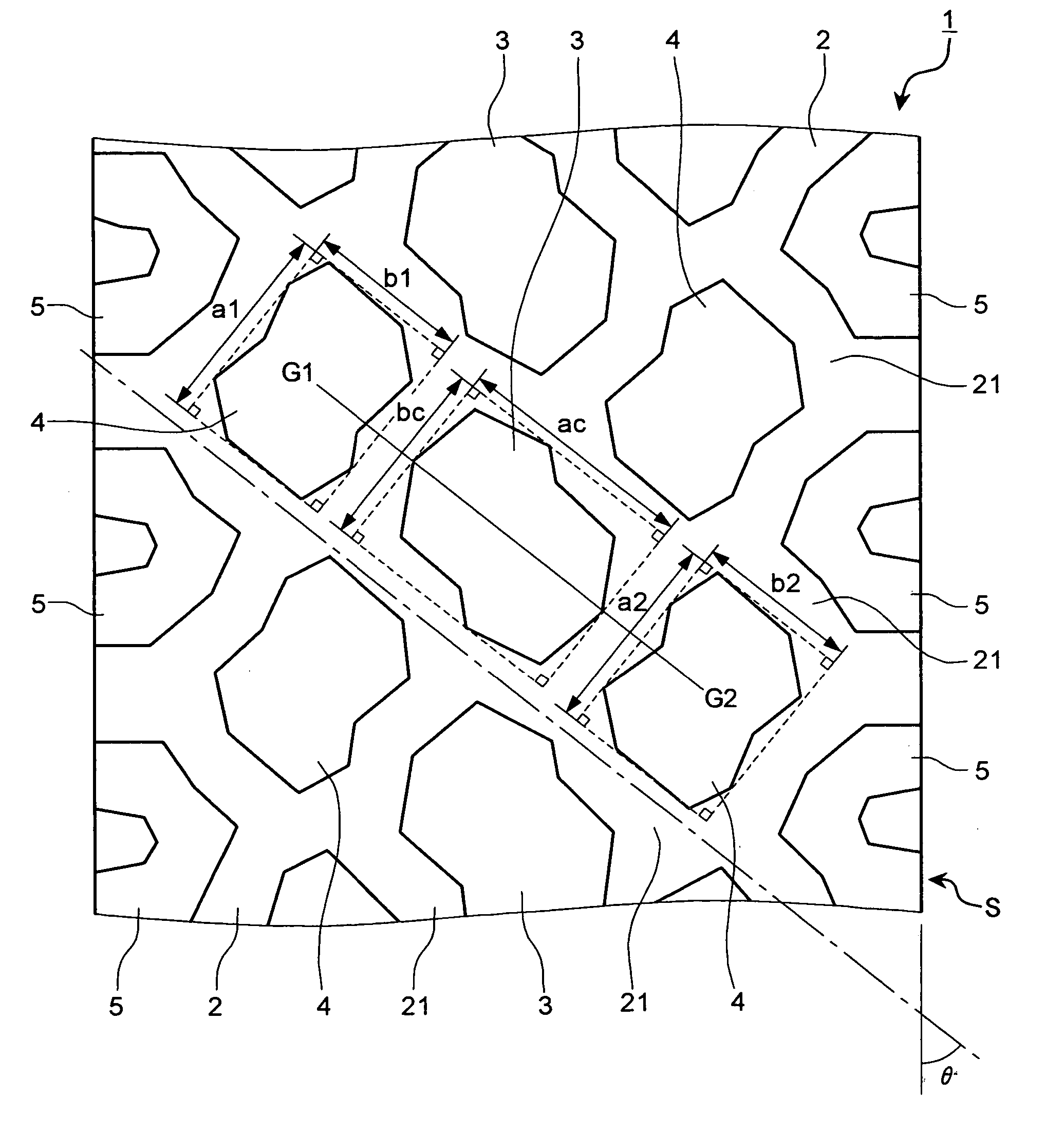
[0012] Exemplary embodiments of the present invention will be explained below in detail with reference to the accompanying drawings. Note that the invention is not limited by the embodiments. Constituent elements described below will include other elements that are easily replaceable by those skilled in the art, or elements that are substantially the same to the described ones.

[0013] A pneumatic tire 1 according to a first embodiment of the present invention is, for example, a pneumatic tire for heavy duty used under both running conditions on snowy roads and unpaved roads. The pneumatic tire 1 has grooves 2 and a tread (or tread face) including blocks 3 to 5.

[0014] The grooves 2 are formed in the form of a web on the tread portion and the grooves 2 include communication grooves 21. The communication groove 21 constitutes a fiber portion extending in a direction of a web woven when the grooves 2 are viewed as the web woven lengthwise and crosswise. The communication grooves 21 are...


PUM


Abstract

In a pneumatic tire, a block unit includes a center block and side blocks separated by a communication groove. Aspect ratios of the center block and the side blocks are approximately the same. The center block and the side blocks are arranged such that a longitudinal direction of a rectangle relating to the aspect ratio of the center block and longitudinal directions of rectangles relating to the aspect ratios of the side blocks are approximately orthogonal to each other. Size ratios of a short side of the rectangle relating to the aspect ratio of the center block and the long sides of the rectangles relating to the aspect ratios of the side blocks are in a range equal to or more than 0.90 to equal to or less than 1.10.

Description

BACKGROUND OF THE INVENTION [0001] 1. Field of the Invention [0002] The present invention relates to a pneumatic tire, and particularly relates to a pneumatic tire having better traction performance and that is resistant to wear. [0003] 2. Description of the Related Art [0004] A conventional pneumatic tire has been disclosed in Japanese Patent Application Laid-open No. 2002-2231. This pneumatic tire has lugs sectioned by lug grooves opened at an end of a tread portion and circumferential grooves of the tire, and has center blocks defined by the circumferential grooves and the lateral grooves. The total length of the lug in a widthwise direction of the tread portion is equal to or more than a corresponding length of the center block and is equal to ¼ or more of the tread width. [0005] However, the conventional pneumatic tire undergoes irregular wear, particularly on unpaved roads. In other words, the conventional pneumatic tire wears more in the central part than at the shoulders. Th...

Claims


Application Information

Patent Timeline
IPC IPC(8): B60C11/11
CPCB60C11/11Y10S152/902
Inventor SUZUKI, TAKAYUKIOYAMA, TOSHIRO
Owner YOKOHAMA RUBBER CO LTD
Why Eureka
Try Eureka