Container and device for generating electric fields in different chambers

a technology of electric field and container, which is applied in the field of container with chamber, can solve the problems of inability to adjust the electric parameter variable, inability to individual chamber operation, etc., and achieve the effect of minimizing the complexity of the contact of electrodes and reducing the difficulty of operation

Active Publication Date: 2006-04-27
LONZA COLOGNE
View PDF10 Cites 32 Cited by
  • Summary
  • Abstract
  • Description
  • Claims
  • Application Information

AI Technical Summary

Benefits of technology

[0009] According to the invention this need is addressed by a container of the kind mentioned above, wherein at least two first electrodes of different chambers are conductively coupled and at least one second electrode of said chamber is separately conductively connectable. Thus, each chamber of a container can be separately selected, controlled and switched, respectively, in an easy manner so that the probes can be exposed to different conditions. With this container according to the invention a lot of samples can be tested under different conditions within a short time, without having to change the container or the probes, so that the container according to the invention is especially suited for automated HT-methods. As some electrodes are conductively connected the technical complexity as far as the contacting of electrodes is concerned can be minimized.
[0010] At least a group of electrodes of the same polarity or all electrodes of the same polarity, i.e. those that have the same polarity if direct current is applied and that are allocated to different chambers, can be conductively coupled so that on the one hand the method according to the invention can be accelerated and on the other hand contacting of the electrodes can be simplified.
[0011] In an advantageous embodiment of the invention specific contact areas that are electrically contactable for the application of said electric voltage are allocated to said electrodes. The at least two coupled electrodes of different chambers are contactable by means of a common contact area. Consequently, manufacturing can be simplified and the amount of necessary electric contacts and wires, respectively, can be minimized.

Problems solved by technology

Such arrangements have the advantage of a relatively simple assembly but, however, it is a disadvantage that the electrical parameter for all chambers is the same and consequently the individual operation of individual chambers is not possible.
As a consequence, even with this known arrangement no variable adjustment of electric parameter is possible so that all reaction areas are exposed to the same electric conditions.

Method used


Image

  • Container and device for generating electric fields in different chambers
  • Container and device for generating electric fields in different chambers
  • Container and device for generating electric fields in different chambers

Examples


Embodiment Construction

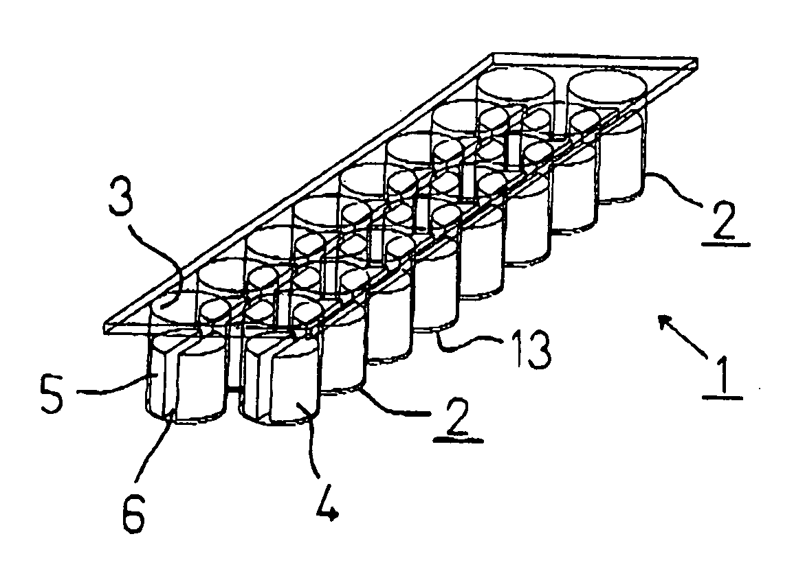
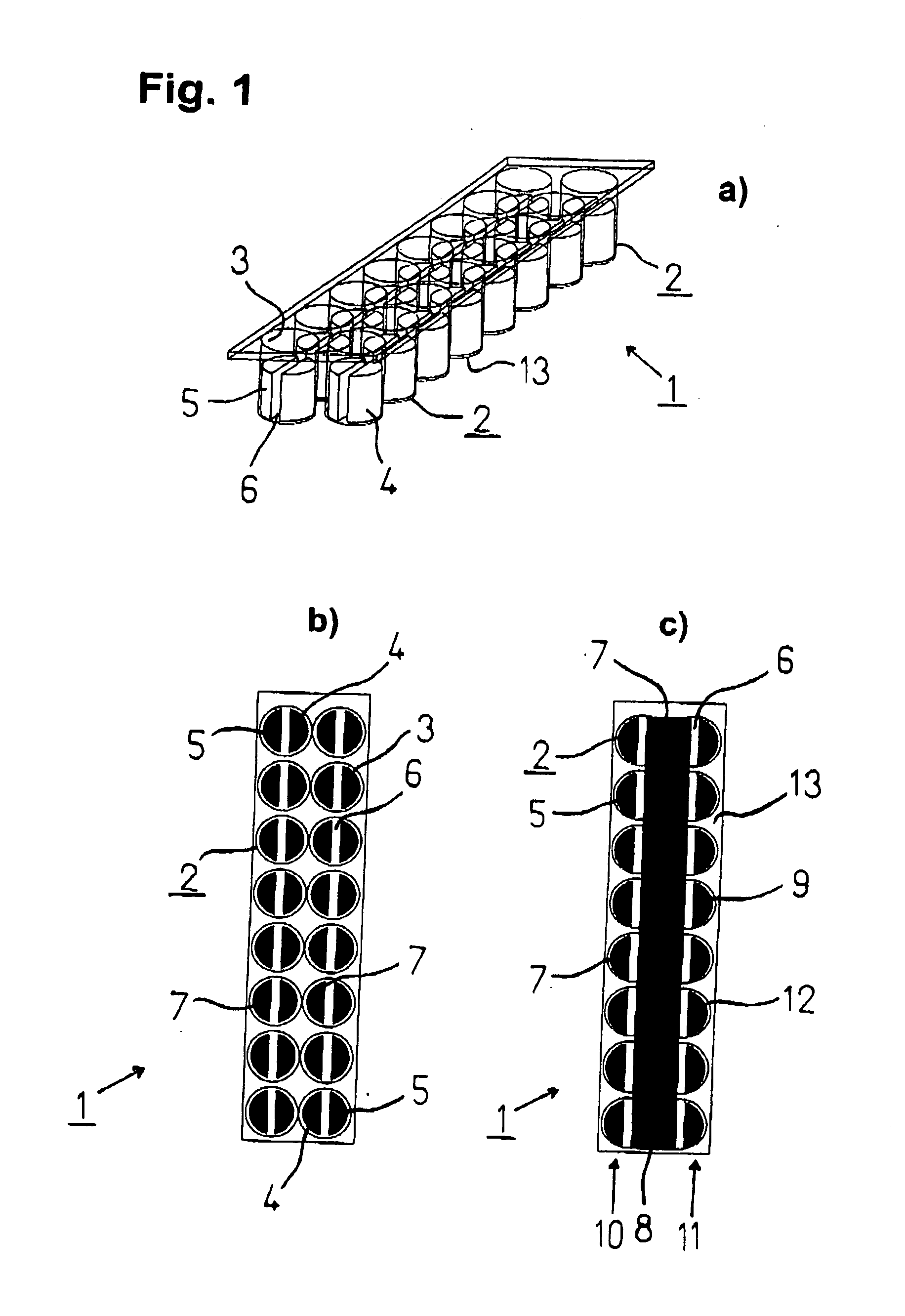
[0052]FIG. 1 shows different views of a particularly advantageous embodiment of a container 1 according to the invention. The container 1 is depicted in a) perspective view, b) top view, and c) bottom view. The container 1 according to the invention comprises 16 chambers 2 which each are built by a wall area 3. Each chamber 2 comprises a pair of electrodes which includes a first electrode 4 and a second electrode 5. While the wall area 3 consists of a non-conductive material, for example glass or plastics, the electrodes 4, 5 are made of an electroconductive material. For example, the electrodes 4, 5 may thereby consist of a metal, i.e. aluminium, copper, silver or gold. However, electrodes made of a polymer which is doped with a conductive material are preferred. In this case, the dope may comprise, for example, fibres of carbon, graphite, carbon black (soot) and / or carbon nanotubes. Said Polymer may comprise a concentration of 40-80% w / w of dope. Such conductive polymers are benef...


PUM

PropertyMeasurementUnit
temperatureaaaaaaaaaa
volumeaaaaaaaaaa
electric voltageaaaaaaaaaa

Abstract

The invention concerns a container 1 with chambers 2 which each comprise at least one pair of electrodes including a first 4 and a second electrode 5 for the application of electric voltage for generating an electric field within one chamber 2. At least two first electrodes 4 of different chambers 3 are conductively coupled and at least one second electrode 5 of said chamber 2 is separately conductively connectable. The invention further concerns a method for manufacturing said container 1 as well as a device for electrically contacting at least one of said containers 1.

Description

[0001] This application claims priority to European application No. 04006058.4, filed Mar. 15, 2004, which is incorporated herein by reference in its entirety. FIELD OF THE INVENTION [0002] The invention concerns a container with chambers which each comprise at least one pair of electrodes including a first and a second electrode for the application of electric voltage for generating an electric field within one chamber. The invention further concerns a method for manufacturing said container as well as a device for electrically contacting at least one of said containers. BACKGROUND OF THE INVENTION [0003] Containers with several chambers of the nature mentioned above are well-established and are mainly used in biochemical and pharmaceutical applications if a plurality of probes has to be tested simultaneously. Special applications are, for example, electroporation, electrofusion and electrostimulation of living cells as well as all applications with which the probe has to be expose...

Claims


Application Information

Patent Timeline
Patent Type & Authority Applications(United States)
IPC IPC(8): B41J2/01B01J19/00B01L3/00C12M1/42C12M3/00C12N13/00
CPCB01J19/0046B01J2219/00315B01J2219/00317B01J2219/00585B01J2219/00599B01J2219/00689C12M35/02B01J2219/00743B01L3/50855B01L2300/0645B01L2300/0829C12M23/12B01J2219/00713C12M1/42C12M3/00
Inventor MULLER-HARTMANN, HERBERTHABIG, MICHAEL
Owner LONZA COLOGNE
Why Eureka
Try Eureka