Tray used in an optical disk drive

Active Publication Date: 2006-05-18
TRANSPACIFIC ELECTRONICS
View PDF6 Cites 2 Cited by
  • Summary
  • Abstract
  • Description
  • Claims
  • Application Information

AI Technical Summary

Benefits of technology

[0004] It is an object of the present invention to provide a tray with a measuring size precision mechanism.
[0005] To achieve the above mentioned object of the present invention, the present invention provides a tray-used in an optical disc drive which comprises: at least two aligning means arranged in a tray and formed

Problems solved by technology

However, as soon as the tray 10 moves, the measuring standard will have deviation, and the tray 10 cannot precisely keep the measuring standard used by the front side and that used by the back side.

Method used


Image

  • Tray used in an optical disk drive
  • Tray used in an optical disk drive
  • Tray used in an optical disk drive

Examples


Embodiment Construction

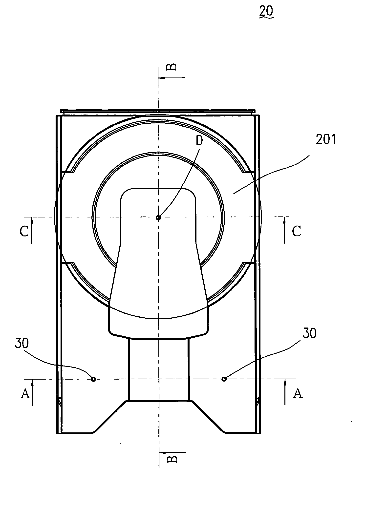
[0011]FIG. 3 shows aligning means arranged in the front side of the tray of the present invention, and FIG. 4 shows a structural diagram of the back side of the tray corresponding to the aligning means in FIG. 3. Each component is respectively arranged on the front side and back side of the tray 20 of the present invention, such as carrier plane 201 for carrying an optical disk, longitudinal rack 203, etc., and aligning means 30 are formed integrally and simultaneously. After the tray 20 is made, e.g. the tray 20 is made of a plastic material in extrusion and formed integrally, for ensuring the made tray 20 completely meets the size of the design specification, it is necessary to measure the tray 20. Since the tray 20 of the present invention has a feature of aligning means 30, the measurer can obtain an aligning line A by drawing a line through the aligning means 30. From the aligning line A obtained on the front side of the tray 20, please refer to the aligning line A shown in FIG...


PUM


Abstract

The present invention relates to a tray used in an optical disc drive. At least two aligning means arranged in the tray and formed integrally with the tray for providing an accordance reference of forming an aligning line at a front side and a back side of the tray, respectively. The aligning line is formed through the aligning means used to measure the precise size of each component arranged at the front side and back side of the tray, respectively.

Description

FIELD OF THE INVENTION [0001] The present invention relates to a tray used in an optical disc drive, and particularly to having aligning means formed integrally with the tray and the aligning line formed through the aligning means used to measure the precise size of each component arranged at the front side and back side of the tray, respectively. BACKGROUND OF THE INVENTION [0002]FIG. 1 shows the structural diagram of a front side of a tray of a conventional optical disc drive, and FIG. 2 shows a structural diagram of a back side of the tray of the FIG. 1. After the conventional tray 10 is made, e.g. the conventional tray 10 made by using an extrusion, the tray 10 has to be measured precisely to make sure the size of each component arranged on the tray 10 and the relative sizes between the components. These sizes must meet a design specification such that they can be really arranged in the optical disc drive. After a measurer finishes measuring each component on the front side of t...

Claims


Application Information

Patent Timeline
IPC IPC(8): G11B17/03G11B17/04G11B33/02
CPCG11B17/051
Inventor LIN, KE RONGCHEN, HSIN-TSO
Owner TRANSPACIFIC ELECTRONICS
Why Eureka
Try Eureka