Integrated air inlet system for multi-propulsion aircraft engines

a multi-propulsion aircraft and air inlet system technology, applied in the field of air breathing engines, can solve the problems of loss of compression efficiency and exposed moving parts that are vulnerable to damage, and achieve the effects of reducing engine weight and volume, sacrificing critical thrust, and increasing atmospheric air volum

Active Publication Date: 2006-05-25
AEROJET ROCKETDYNE INC
View PDF21 Cites 24 Cited by
  • Summary
  • Abstract
  • Description
  • Claims
  • Application Information

AI Technical Summary

Benefits of technology

[0007] This invention therefore resides in integrated air ducts for combined-cycle engines and in combined-cycle engines themselves that incorporate these integrated air ducts. In the combined-cycle engines, the low-speed component is either one or more turbojets, one or more rockets, or a combination of rockets and turbojets. Such a combination allows the use of a smaller turbine engine(s) without sacrificing critical thrust during the takeoff and transition stages. One advantage of the integrated air ducts of this invention and the engines in which they are used relative to the prior art is that all incoming air is utilized during all stages of takeoff and acceleration, thereby allowing the use of a larger volume of atmospheric air for combustion at any single stage. This also reduces the weight and volume of the engine as a whole. Another advantage of the engines of this invention is that the arrangement of internal channels and movable panels allows air to enter the high-speed channel while the vehicle is still traveling at a relatively low Mach number, and the movement of the panels provides a smooth transition between the stages. A third advantage is that the movable panels can be constructed without leading edges that are exposed to the high enthalpy air flow. This permits the panels and the engine as a whole to be of more durable construction and to reduce the generation of shock waves that prevent air from entering the engine. The ability to allow air to enter the high-speed engine while the low-speed engine is still operating, the higher mass capture of atmospheric air, the improved pressure recovery, and the reduction in drag caused by the spill of atmospheric air at all speeds collectively result in an engine with a thrust and a specific impulse (Isp) that are significantly higher than those of many combined-cycle systems of the prior art.

Problems solved by technology

The booster-to-ramjet transition is a critical stage in the operation of the engine since any loss of air flow through either engine during the transition can result in a loss of compression efficiency.
The need to shift inlet air from the booster propulsion system to the high-speed propulsion system has resulted in large geometries that create flow resistance, surfaces and leading edges that produce complex shock waves, areas of separated or recirculating flow, and exposed moving parts that are vulnerable to damage.

Method used


Image

  • Integrated air inlet system for multi-propulsion aircraft engines
  • Integrated air inlet system for multi-propulsion aircraft engines
  • Integrated air inlet system for multi-propulsion aircraft engines

Examples


Embodiment Construction

[0016] While this invention covers a wide range of configurations, geometries, and applications, an understanding of the features that are common to all embodiments and that define the invention and its operation as a whole can be obtained by a review of specific examples. The drawings accompanying this specification and their description below relate to several such examples; others will be readily apparent to those skilled in the art.

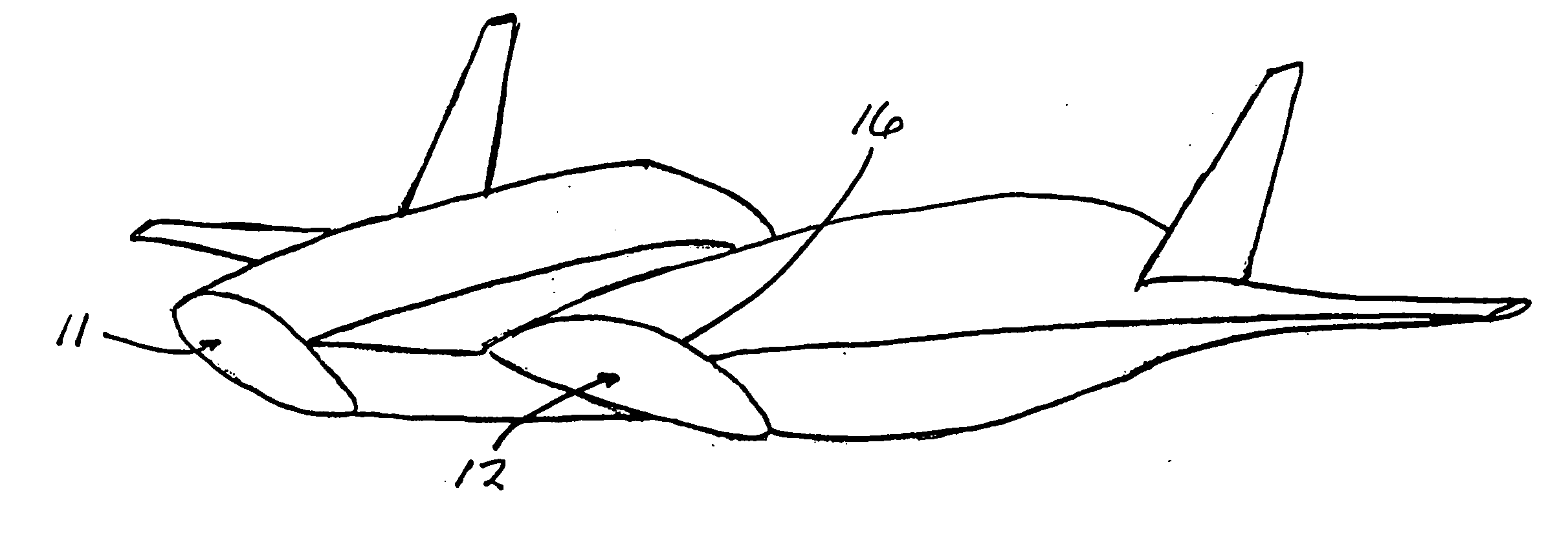
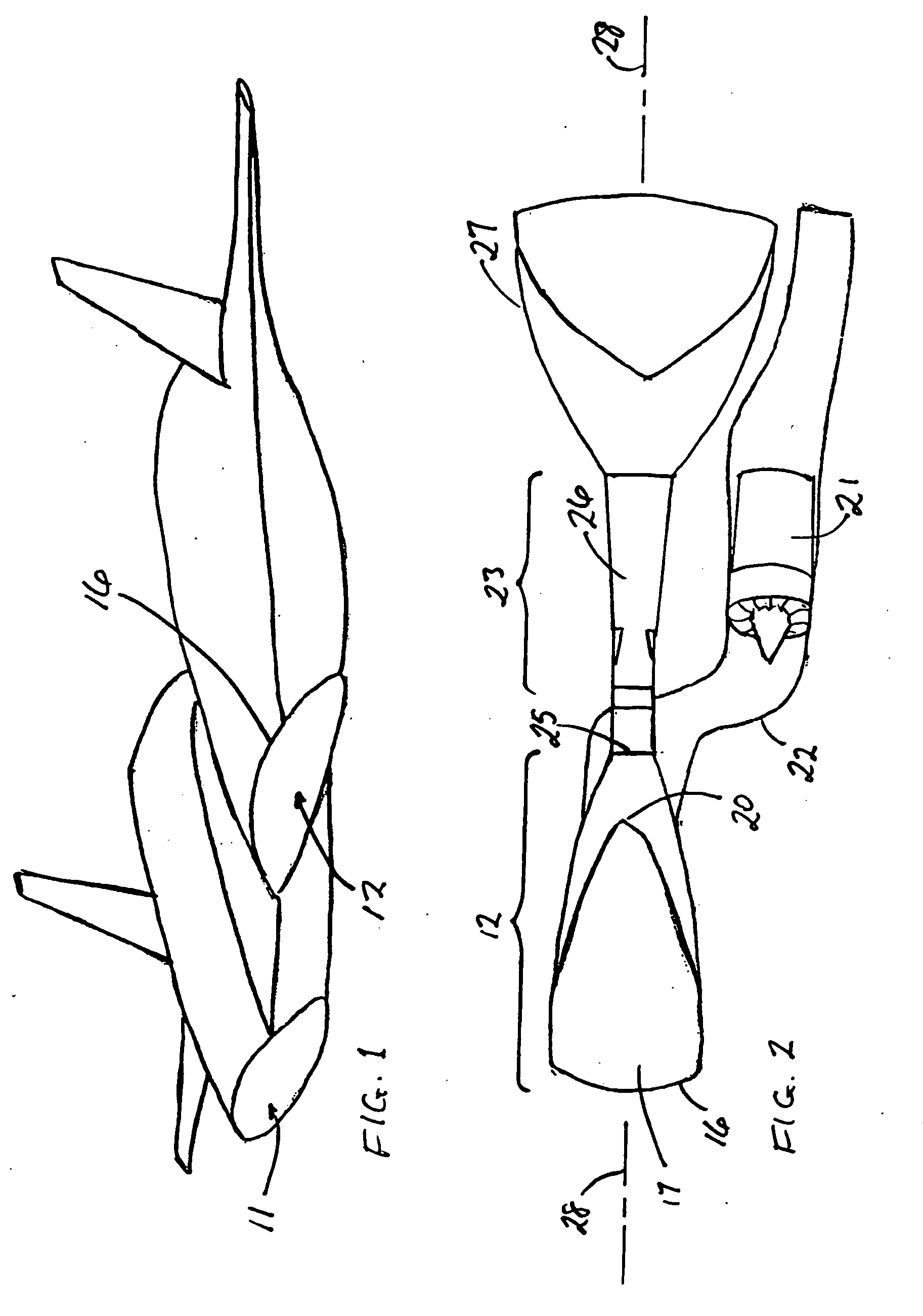
[0017] A front view of a vehicle containing engines and integrated air ducts in accordance with the present invention is shown in FIG. 1. The vehicle contains two combined-cycle engines with a separate air inlet 11, 12 for each. Inside each of the air inlets are throats of circular cross section that lead to the ramjet engine components. The air inlets 11, 12 are not vertically centered in the vehicle body but instead offset toward the bottom of the vehicle. The opening 16 of each inlet follows the aerodynamically shaped contour of the vehicle, and t...


PUM


Abstract

An air inlet duct for an air-breathing combined-cycle aircraft engines is internally divided into separate channels for low-speed and high-speed components of the engine, and contains one or more movable panels that are fully contained within the duct and pivotal between an open position in which incoming air is directed to both channels and a closed position in which all incoming air is directed to the channel leading to the high-speed engine. This integrated duct utilizes all incoming air at all stages of flight with no change in either the geometry of the air capture portion of the engine or the engine itself, and no exposure of movable leading edges. The result is a minimum of shock waves and a high degree of efficiency in operation of the engine.

Description

BACKGROUND OF THE INVENTION [0001] 1. Field of the Invention [0002] This invention resides in the field of air-breathing engines, and particularly combination engines that incorporate both a ramjet component and a low-speed booster component such as a rocket or a turbojet. [0003] 2. Description of the Prior Art [0004] Air-breathing engines for hypersonic applications are known as “combined cycle” systems because they use a graduating series of propulsion systems in flight to reach an optimum travel speed or to leave the atmosphere altogether. Air-breathing engines use atmospheric air as a source of oxygen for combustion, as opposed to rockets which carry their own oxidizer. By using air captured from the atmosphere, air-breathing systems are several times more efficient than conventional rockets. [0005] The thrust upon takeoff of a combined cycle engine and operation of the engine at low-to-moderate Mach numbers is achieved by a booster unit which consists of either rockets or turbo...

Claims


Application Information

Patent Timeline
Patent Type & Authority Applications(United States)
IPC IPC(8): F02K9/78F02K99/00
CPCB64C30/00B64D33/02F02C7/042F02K7/10F02K7/14F02K7/16F02K9/18F05D2220/34Y10T137/0536
Inventor BULMAN, MELVIN J.BILLIG, FREDERICK S.
Owner AEROJET ROCKETDYNE INC
Why Eureka
Try Eureka