
Eureka
For R&D, Eureka makes reading and utilizing patents & technical documents easy.
Eureka AIR
Designed for self-driven R&D workflows. Generate viable solutions, solve complex R&D challenges, empower your innovation with AI.

Eureka Materials
Designed for material experts only. Revolutionize your material R&D, from search, analyze, to developing new materials.

TechResearch
Generate reliable direction feasibility study reports for your R&D in just a few steps.

TechSeek
Discover and master advanced knowledge NOW. Basics, ideas, possibilities, all at once.

TechMind
As an expert in R&D Theories, TechMind can generates customized viable solutions instantly.

TechRisk
Analyze your overall solution with one click, know your potential R&D risks in advance.

TechMonitor
Get weekly tech updates, stay abreast of the latest tech innovations and key insights.
Switch
- Summary
- Abstract
- Description
- Claims
- Application Information
AI Technical Summary
Benefits of technology
Problems solved by technology
Method used
Image

Examples
first embodiment
[0045] The following is a description of the operation of a
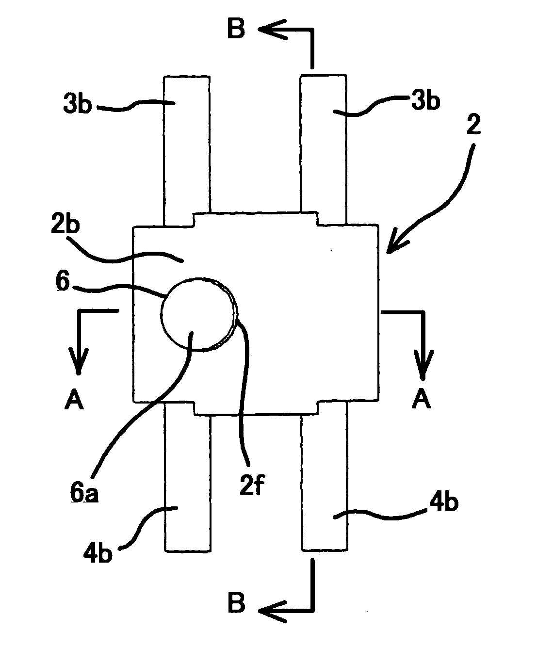
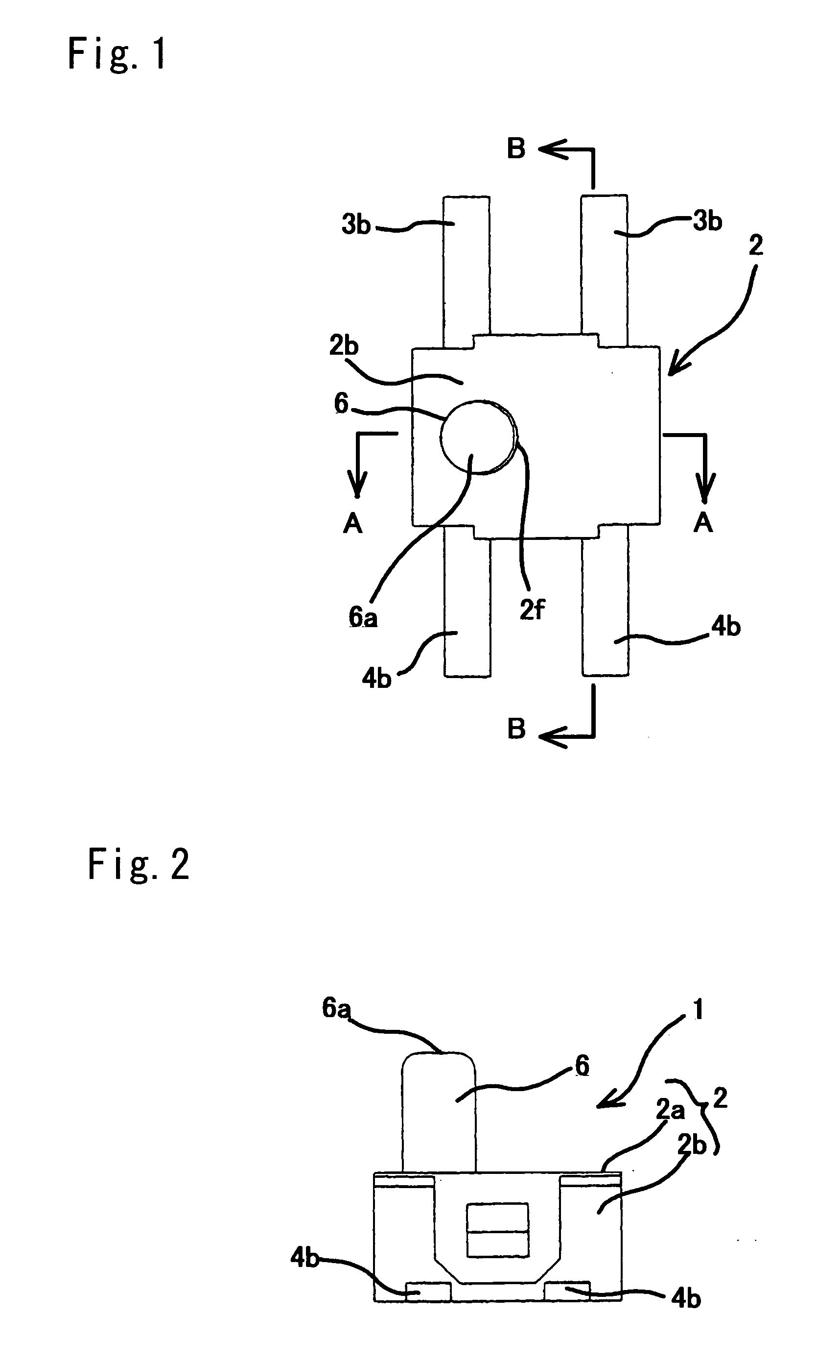
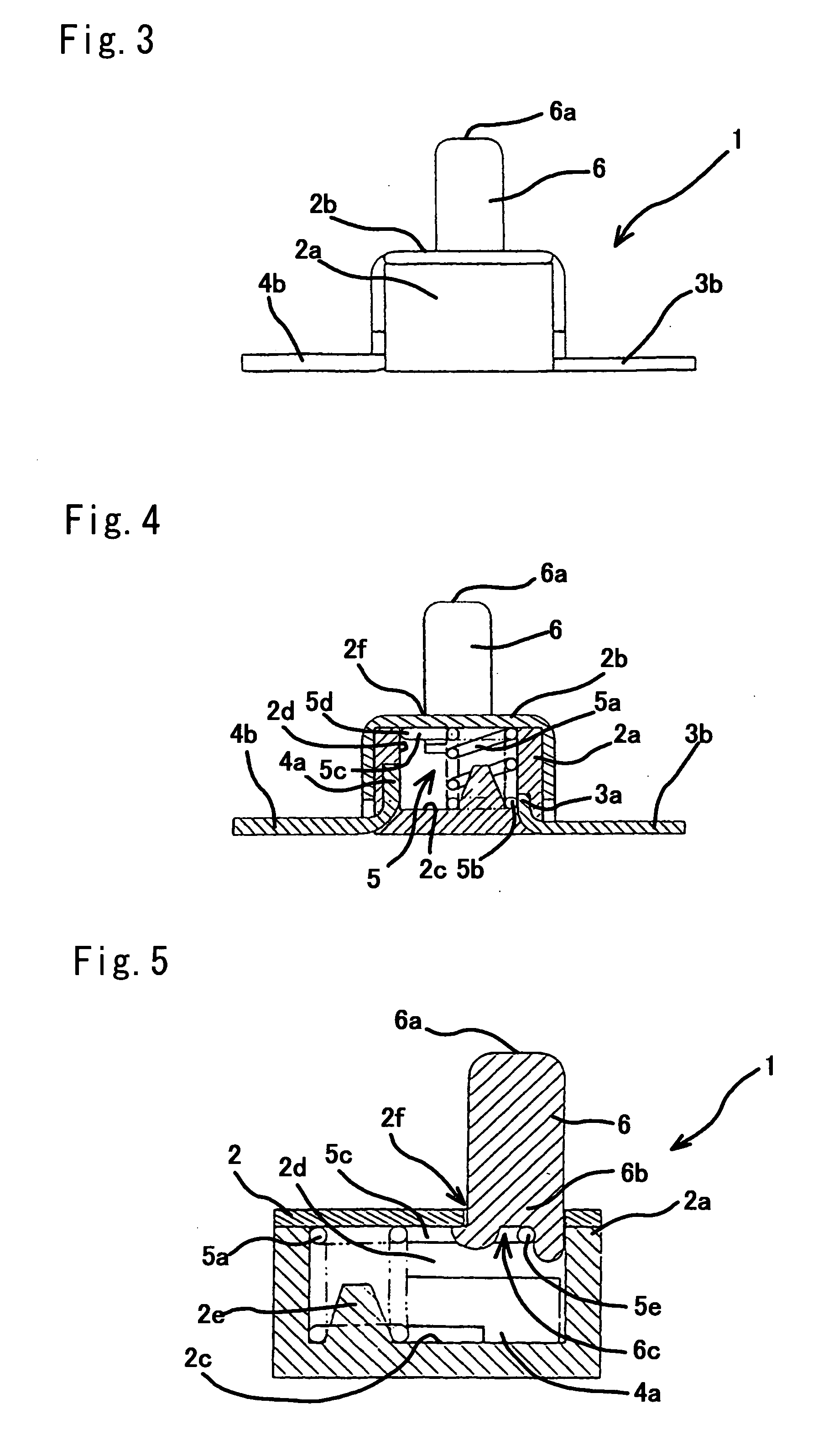
[0046] The switch 1 presses against a pressing section 6a of the operation body 6 in a state fitted at a prescribed position of the circuit substrate etc.
[0047] In doing so, the operation body 6 slides within the hole 2f of the cover 2b. When the operation body 6 slides, the tip rectilinear section 5e of the movable contact section 5c is inserted into the groove 6c of the operation body 6. The coil spring section 5a of the contact piece 5 therefore moves in a direction so as to be compressed in the direction of arrow C and the point of operation to the contact piece 5 becomes the tip rectilinear section 5e away from the coil spring section 5a. The coil spring section 5a therefore buckles. The curved section 5d of the movable contact section 5c moves while making contact with the side surface 2d within the case body 2a, makes contact with the contact point 4a of the second fixing terminal 4, and a state is attained where the...
second embodiment
[0050] With the switch 1 of the second embodiment, a cover 2b is not provided but rather the operation body 6 doubles as the cover 2b.
[0051] The operation body 6 is comprised of a plate-shaped body substantially the same shape as the opening of the case body 2a and forms the pressing section 6a constituting a mountain-shaped projection having a gradual incline at the upper surface end of the operation body 6. A central projection 6d projects centred about a centre of swing where swinging of the pressing section 6a is possible at both sides on the opposite side to the pressing section 6a of the operation body 6. The coil spring section 5a and the movable contact section 5c come into contact at the time of fitting of the case body 2a at the surface opposite to the pressing section 6a of the operation body 6, with this opposing surface forming the operation section 6b.
[0052] Further, the case body 2a latching the operation body 6 is formed in a substantially boxed shape with one end ...
PUM
 Abstract
Description
Claims
Application Information
 - R&D Engineer
- R&D Manager
- IP Professional
- Industry Leading Data Capabilities
- Powerful AI technology
- Patent DNA Extraction
Browse by: Latest US Patents, China's latest patents, Technical Efficacy Thesaurus, Application Domain, Technology Topic, Popular Technical Reports.
© 2024 PatSnap. All rights reserved.Legal|Privacy policy|Modern Slavery Act Transparency Statement|Sitemap|About US| Contact US: help@patsnap.com