Systems and methods for a continuously variable optical delay line

a continuously variable, delay line technology, applied in the direction of optical light guides, optical waveguide light guides, instruments, etc., can solve the problem that the continuous delay line loses virtually no information when the continuous delay changes, and achieves the effect of high and tunable time-bandwidth components, improved communication, and reduced cos

Inactive Publication Date: 2006-06-29
NORTHROP GRUMMAN SYST CORP
View PDF9 Cites 13 Cited by
  • Summary
  • Abstract
  • Description
  • Claims
  • Application Information

AI Technical Summary

Benefits of technology

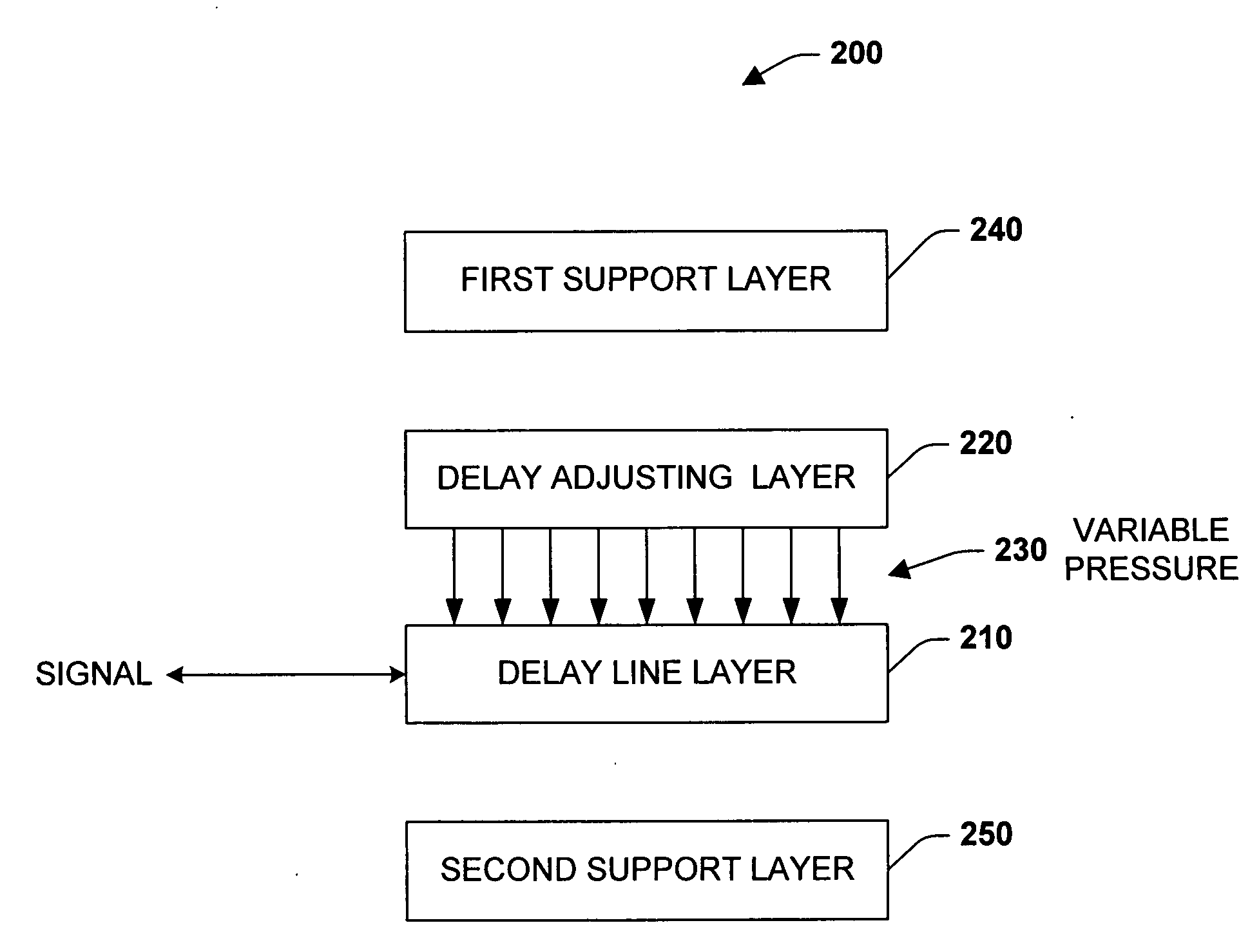
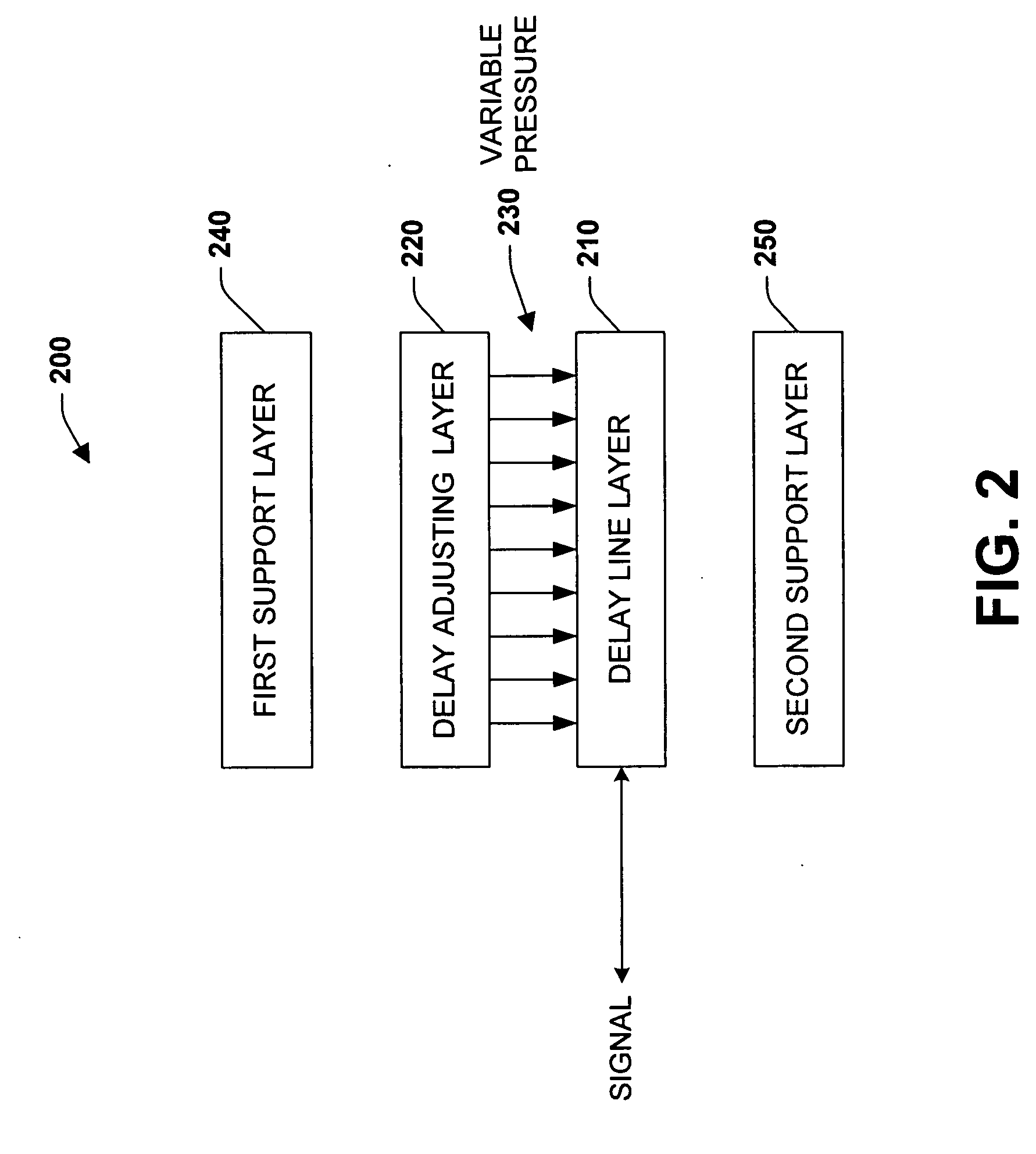
[0012] The present invention provides systems and methods that facilitate the manifestation of a true time delay in a transmitted signal via a employing a continuously variable optical delay line in connection with the transmission of the signal. The systems and methods utilize a novel delay line that includes a hollow core holey fiber, a reflective fluid and a segmented piezoelectric device, wherein the piezoelectric device utilizes a commutated technique to position the reflective fluid in the holey fiber in a continuous, rather than a discrete, manner. The position of the reflective fluid within the fiber determines the effective length of the holey fiber, which is indicative of the delay that can be introduced to the signal.
[0013] The novel delay line of the present invention provides an improvement for communications processors through its extremely high and tunable time-bandwidth. For example, unlike switched binary combination techniques that employ discrete delay changes and that are susceptible to photon loss, the continuously variable delay line loses virtually no information when continuous delay changes are effected. In addition, and unlike switched binary combination techniques, the delay can be accurately referenced to the wavelength, thereby making a very stable and accurate delay possible (e.g., within ¼ of the optical carrier's wavelength).
[0014] In general, a delay is introduced into an optical signal via directing the signal through an input port operative to the holey fiber, wherein the signal propagates away from the input port until it becomes incident with a reflective fluid in the holey fiber. The signal reflects off the surface of the reflective fluid and travels back towards the input port, thereby doubling the effective time delay for the length of fiber. The delay introduced to the signal is a function of the traveled distance, and thus the position of the reflective fluid within the holey fiber determines the delay. Thus, the holey fiber can be employed as the transmission line for wideband true time delay.

Problems solved by technology

For example, unlike switched binary combination techniques that employ discrete delay changes and that are susceptible to photon loss, the continuously variable delay line loses virtually no information when continuous delay changes are effected.

Method used


Image

  • Systems and methods for a continuously variable optical delay line
  • Systems and methods for a continuously variable optical delay line
  • Systems and methods for a continuously variable optical delay line

Examples


Embodiment Construction

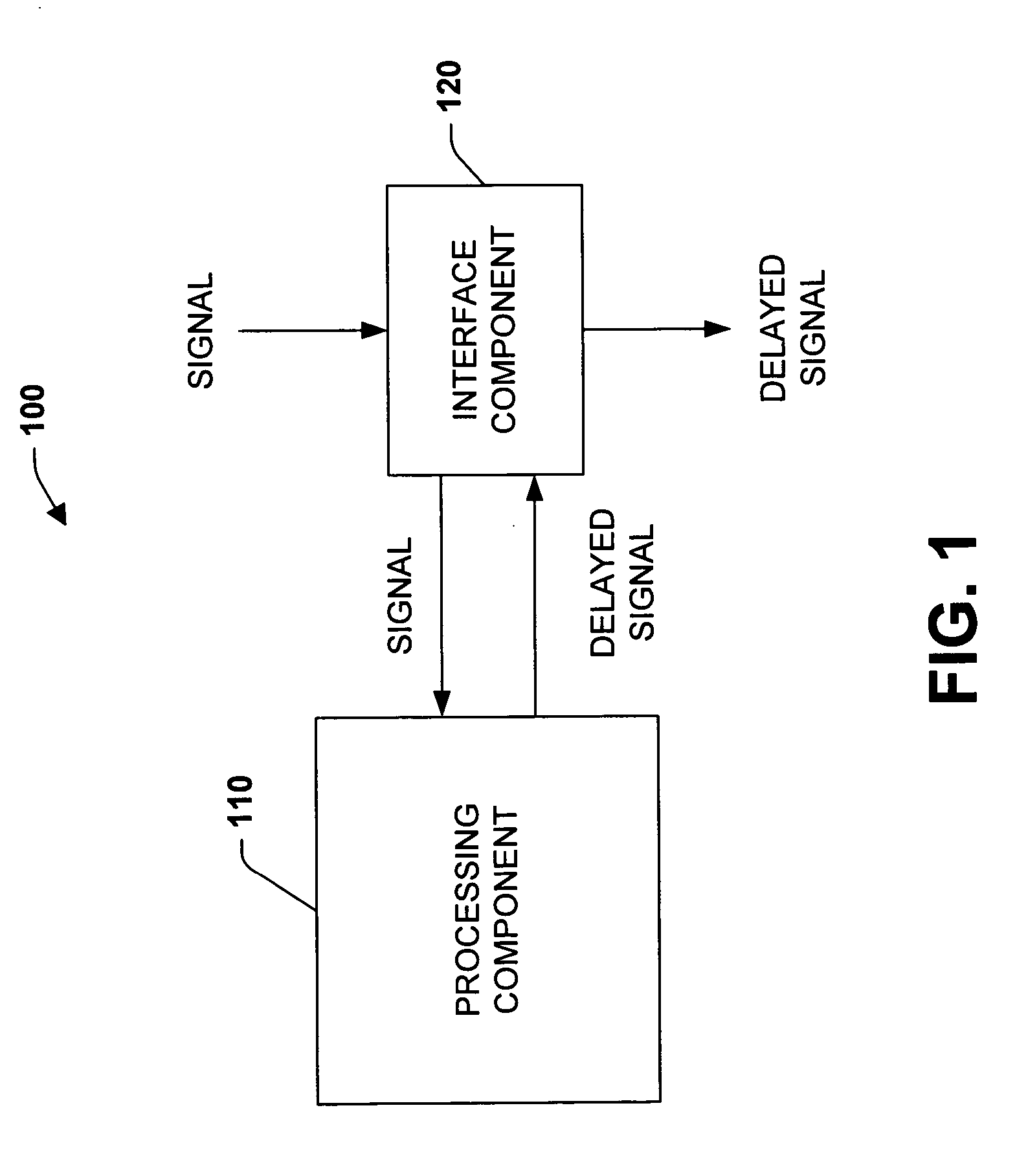
[0035] The present invention provides systems and methods that employ a continuously variable optical delay line to introduce a delay in a transmitted optical signal. In many instances, such systems and methods can be utilized to increase a communication system's performance via providing a wide bandwidth signal delay over a long adjusted duration. By way of example, the systems and methods of the present invention can be employed to provide a high time-bandwidth product delay line that processes narrowband signals in wide spectra. Additional capabilities include true time delay beam forming with very long baselines that yield high accuracy angle of arrival detection and continuously variable programmable delay with high resolution and accuracy that provides repeatability and stability over long time periods and wide temperature ranges. In addition, the systems and methods of the present invention can be relatively inexpensive, compact in size, and rugged in construction.

[0036] The...


PUM


Abstract

The present invention provides systems and methods that employ a continuously variable optical delay line to introduce a delay into a transmitted optical signal. The delay line comprises a holey fiber configured in a spiral layout, wherein one end of the fiber is operative to a reflective fluid reservoir and the other end in operative to an input port. A segmented piezoelectric actuator is employed to position a reflective fluid within the fiber, utilizing a commutated technique that continuously moves the fluid. A signal received at the input port is routed through the holey fiber at an angle of incidence to achieve total internal reflection. The signal traverses towards the reflective fluid, and reflects back towards the input port after coming into contact with the fluid's surface. The delay introduced into the signal is a function of the distance traveled through the delay line.

Description

CROSS-REFERENCE TO RELATED APPLICATIONS [0001] This application is a divisional of U.S. patent application Ser. No. 10 / 636,007, filed Aug. 7, 2003 and entitled “SYSTEMS AND METHODS FOR A CONTINUOUSLY VARIABLE OPTICAL DELAY LINE”, the entirety of which is incorporated herein by reference.BACKGROUND OF THE INVENTION [0002] 1. Field of the Invention [0003] The present invention relates to systems and methods for signal processing, and in particular for delaying a signal via a continuously variable optical delay line. [0004] 2. Discussion of the Related Art [0005] The technical pursuit to provide transmission media with greater bandwidth and higher data rates to efficiently and reliably convey signals (e.g., video and / or audio) has lead to increased research and development in the fiber optics domain and the deployment of fiber optic channels, interfaces and associated devices. Since the invention of the telegraph, there has been a constant push to provide data at higher and higher rate...

Claims


Application Information

Patent Timeline
Patent Type & Authority Applications(United States)
IPC IPC(8): G02B6/032G02B6/00G02B6/02G02B6/28G02B6/35
CPCG02B6/02328G02B6/02366G02B6/02385G02B6/3578G02B6/2861G02B6/3538G02B6/3574G02B6/0239
Inventor UPTON, ERIC LAWRENCE
Owner NORTHROP GRUMMAN SYST CORP
Why Eureka
Try Eureka