Identification connector for a medical laser handpiece

a technology of identification connector and laser handpiece, which is applied in the electromagnetic field, can solve the problems of patient discomfort, damage to the treated tissue, and unsatisfactory consequences

Inactive Publication Date: 2006-06-29
BIOLASE TECH INC
View PDF14 Cites 231 Cited by
  • Summary
  • Abstract
  • Description
  • Claims
  • Application Information

AI Technical Summary

Problems solved by technology

Accidental use of a handpiece not properly matched to an intended medical or dental procedure could lead to undesirable consequences, including patient discomfort, damage to treated tissue, lost time, and the like.

Method used


Image

  • Identification connector for a medical laser handpiece
  • Identification connector for a medical laser handpiece
  • Identification connector for a medical laser handpiece

Examples


Embodiment Construction

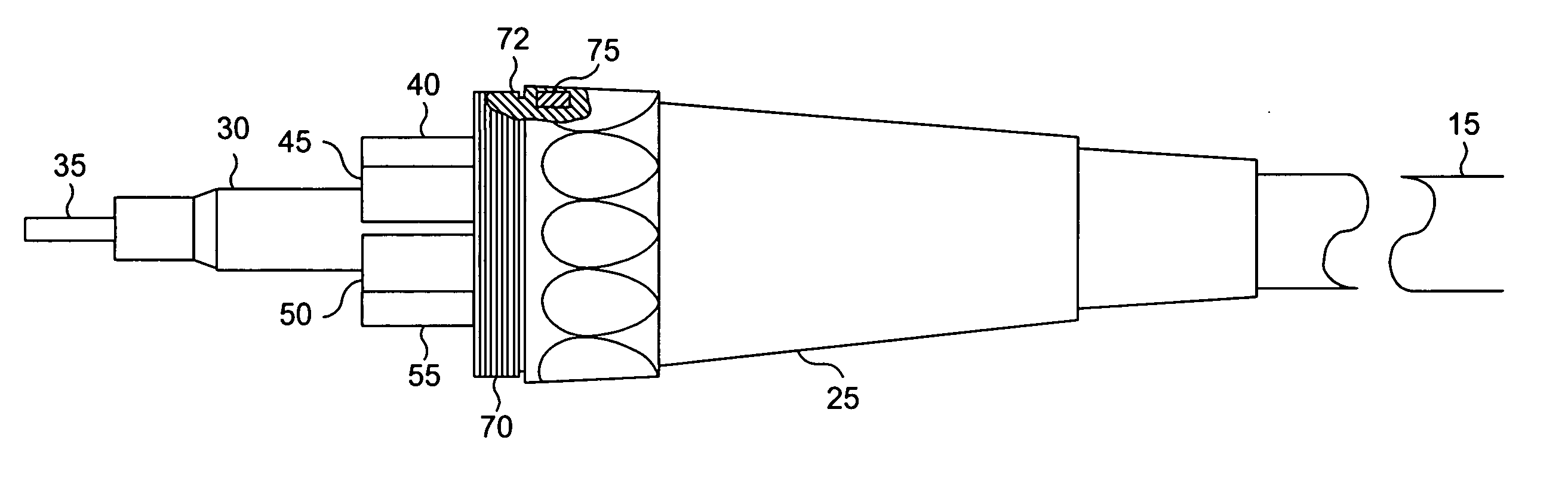
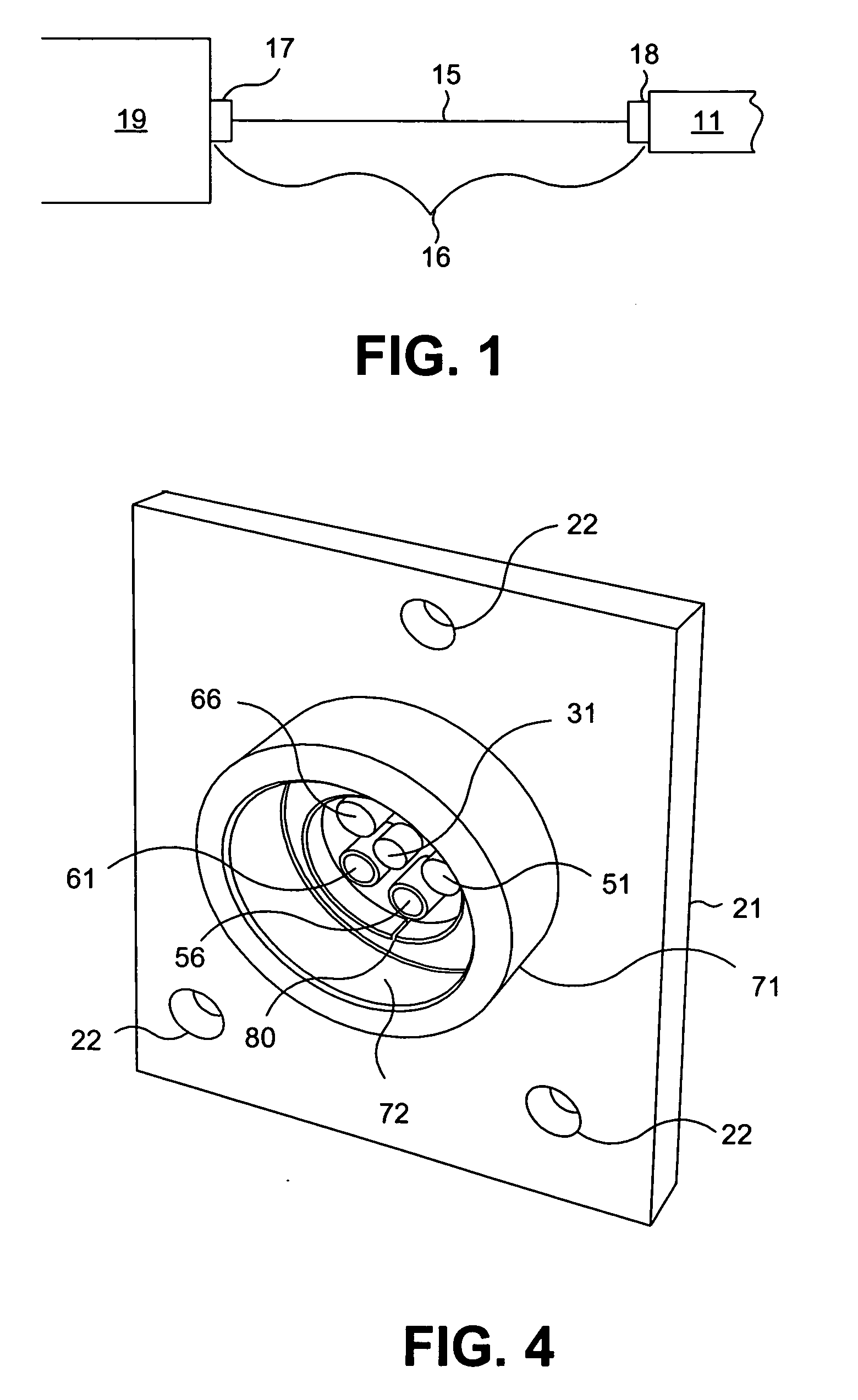
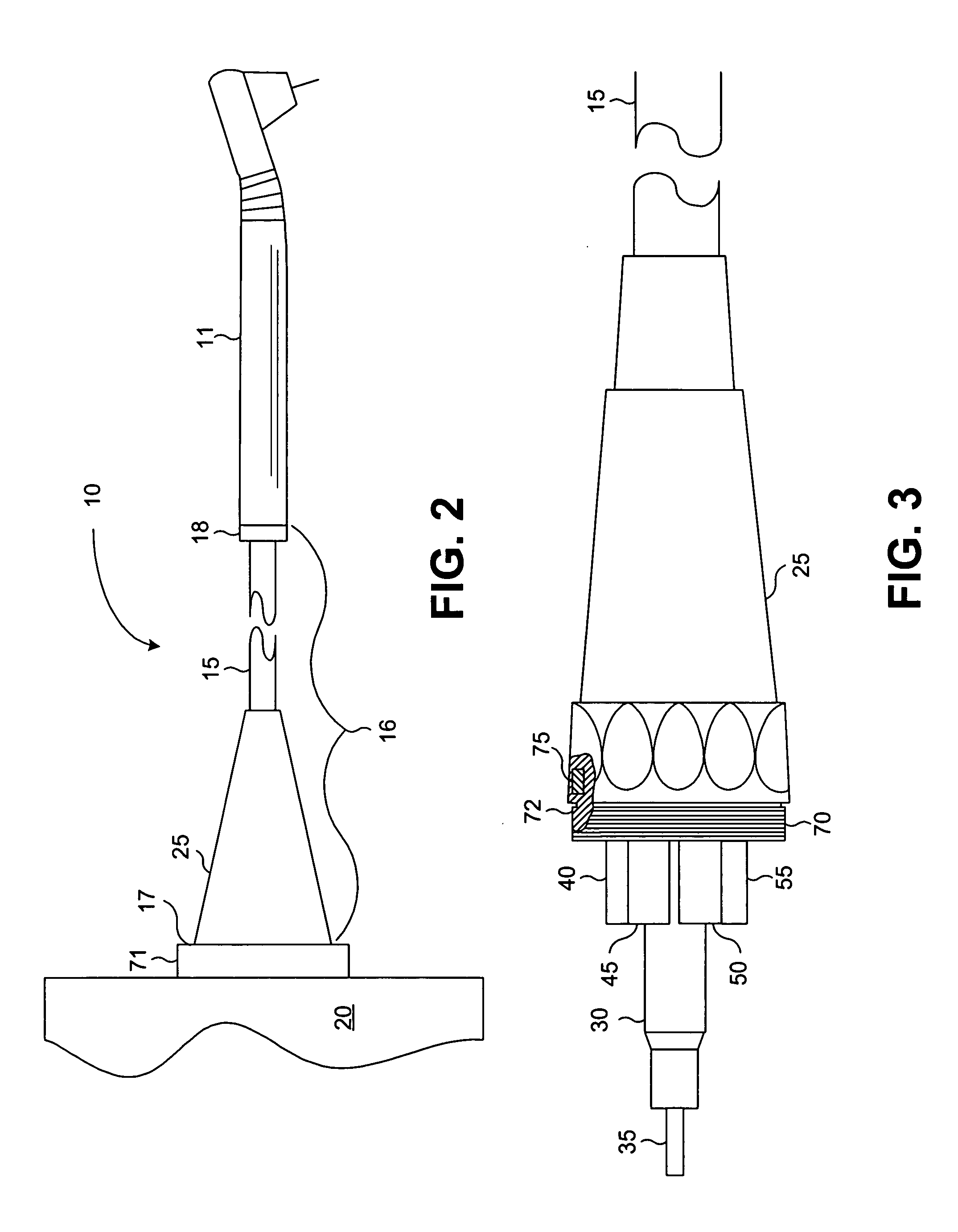
[0022] Reference will now be made in detail to the presently preferred embodiments of the invention, examples of which are illustrated in the accompanying drawings. Wherever possible, the same or similar reference numbers are used in the drawings and the description to refer to the same or like parts. It should be noted that the drawings are in simplified form and are not to precise scale. In reference to the disclosure herein, for purposes of convenience and clarity only, directional terms, such as, top, bottom, left, right, up, down, over, above, below, beneath, rear, and front, are used with respect to the accompanying drawings. Such directional terms should not be construed to limit the scope of the invention in any manner.

[0023] Although the disclosure herein refers to certain illustrated embodiments, it is to be understood that these embodiments are presented by way of example and not by way of limitation. The intent of the following detailed description, although discussing ...


PUM


Abstract

An identification connector is disclosed that provides a link between a laser housing and a laser handpiece. The connector integrates a laser delivery guide with ancillary connections and provides information for verifying proper connection and protection against use of unauthorized delivery systems.

Description

CROSS-REFERENCE TO RELATED APPLICATIONS [0001] This application claims the benefit of U.S. Provisional Application No. 60 / 591,679, filed Jul. 27, 2004 and entitled IDENTIFICATION CONNECTOR, the entire contents of which are incorporated herein by reference. This application relates to U.S. Application No. 60 / 591,933, filed Jul. 27, 2004 and entitled CONTRA-ANGLE ROTATING HANDPIECE HAVING TACTILE FEEDBACK TIP FERRULE, the entire contents of which are incorporated herein by reference.BACKGROUND OF THE INVENTION [0002] 1. Field of the Invention [0003] The present invention relates generally to electromagnetic energy emitting devices and, more particularly, to electromagnetic energy emitting devices that connect to various types of handpieces. [0004] 2. Description of Related Art [0005] Laser devices used in dental and medical applications frequently employ handpieces that are specialized according to dental / medical applications. For example, a laser device and associated handpiece inten...

Claims


Application Information

Patent Timeline
Patent Type & Authority Applications(United States)
IPC IPC(8): A61B18/18A61C1/00A61C3/00
CPCA61B18/22A61B2017/00482A61B2018/00988A61B2019/4815A61C1/0007A61C1/0046A61B2018/225A61B2090/0803A61B90/90
Inventor BOUTOUSSOV, DMITRI
Owner BIOLASE TECH INC
Why Eureka
Try Eureka