Cardiac rhythm management with interchangeable components

Inactive Publication Date: 2006-07-06
PACESETTER INC
View PDF79 Cites 82 Cited by
  • Summary
  • Abstract
  • Description
  • Claims
  • Application Information

AI Technical Summary

Benefits of technology

[0013] In some pacemakers, the lead further incorporates one or more physiological sensors. The lead must then also provide the electrical connections required to power the sensor(s) and to return the physiological sensor signal back to the pacemaker generator. One disadvantage with such multiple function pacemaker leads is the that increased number of electrical conductors required within the lead forces the lead to be larger in diamete

Problems solved by technology

Although sharing of electrodes for pacing and sensing is common, it does have limitations.
Moreover, following each pacing pulse there is a time interval during which sensing cannot take place because the relatively high pacing pulse voltage persists for some time due to capacitance in the lead.
Thus, potentially important electrophysiological data may be lost during this interval with presently available pacemaker technology.
However, in some cases, such a lead would conventionally require separate sensing and pacing conductors as well, which would disadvantageously require the lead diameter to be increased.
One disadvantage with such multiple function pacemaker leads is the that increased number of electrical conductors required within the lead forces the lead to be larger in diameter

Method used


Image

  • Cardiac rhythm management with interchangeable components
  • Cardiac rhythm management with interchangeable components
  • Cardiac rhythm management with interchangeable components

Examples


example 1

A. EXAMPLE 1

[0368] Exemplary modes of operation for an embodiment of the system of the invention are described as follows. The following Example illustrates various embodiments of the present invention and is not intended in any way to limit the invention.

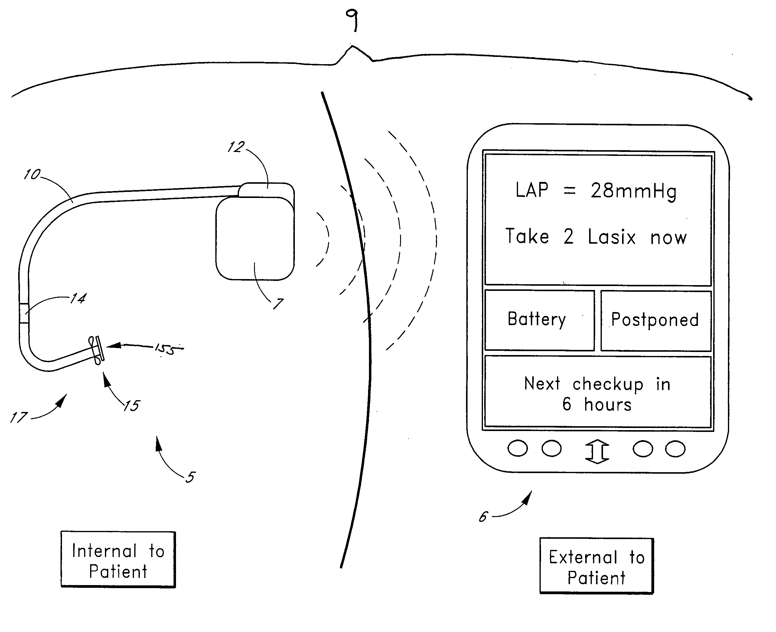
[0369] In one embodiment, the system is programmed to power up once per hour to measure the left atrial pressure and other conditions as dictated by the configuration of the particular system and any other sensors that might be present. Left atrial pressure measurements are taken at a 20-Hertz sampling rate for sixty seconds, yielding 1200 data values reflective of the fluid pressure within the left atrium. The central processing unit then computes the mean left atrial pressure based on the stored values. Then, if the mean pressure is above a threshold value predetermined by the patient's physician, the central processing unit causes an appropriate communication to be sent to the patient via the patient signaling device.

[0370] A ...

example 2

B. EXAMPLE 2

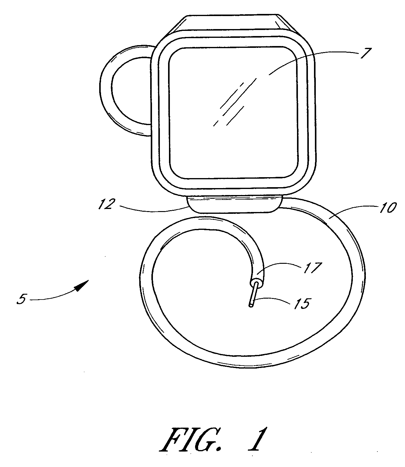
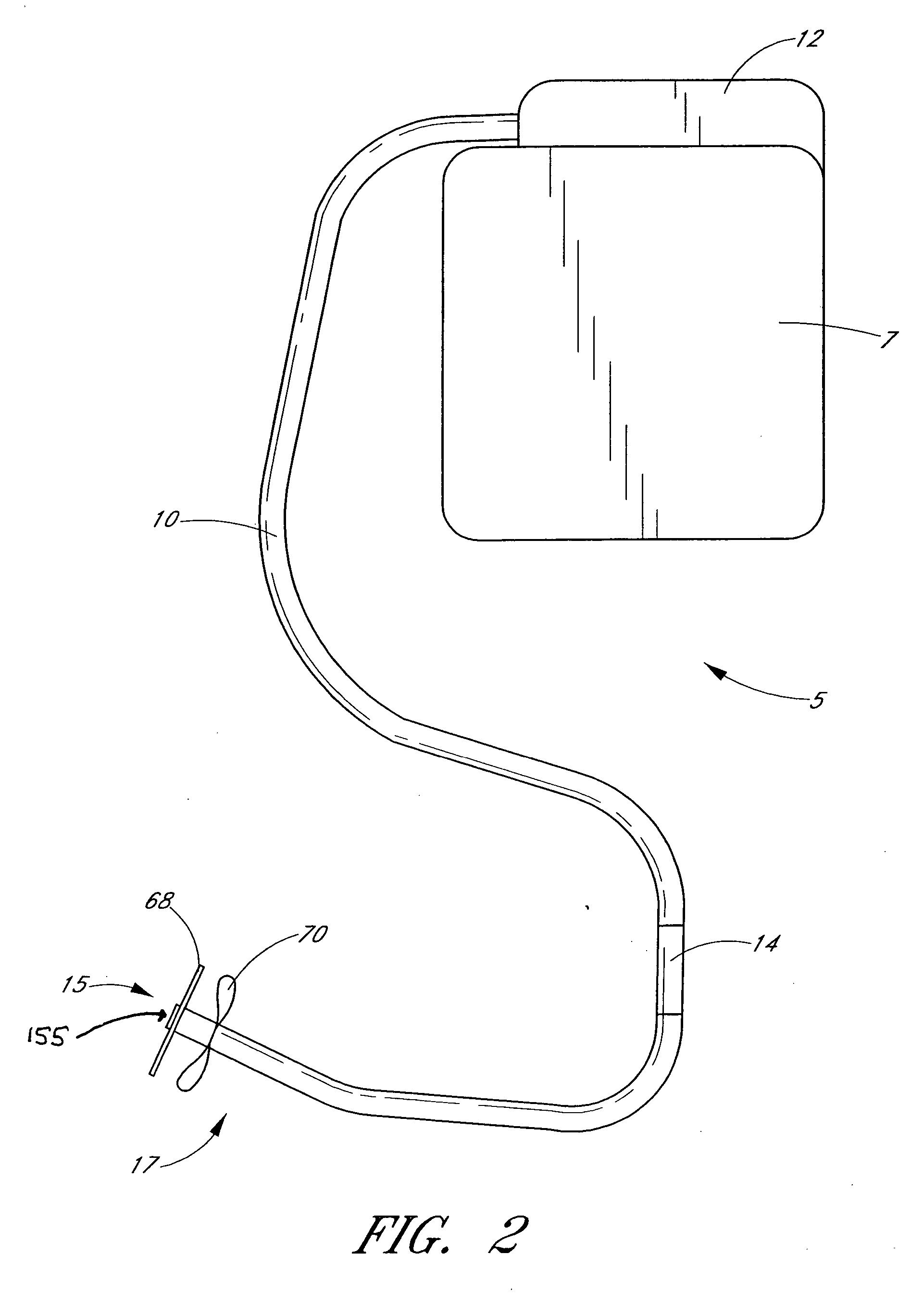
[0378] In one embodiment, the system is configured as an externally powered implantable device with a sensor implanted in the intra-atrial septum. The pressure transducer of the sensor is exposed to the pressure in the left atrium. In one embodiment, the sensor is anchored in the septum such that the pressure transducer is substantially flush with the left atrial wall in fluid contact with blood in the left atrium. In another embodiment, the anchor is designed such that the pressure sensor extends a predetermined distance into the left atrium. In both these embodiments, the pressure sensor package is located in the septum with its proximal end extending back into the right atrium. A flexible lead extends from the proximal end of the sensor package back through the right atrium, into the superior vena cava, up to a subclavian vein, and out through the wall of the subclavian vein, terminating at an antenna coil assembly located in a subcutaneous pocket near the patient's c...

example 3

C. EXAMPLE 3

[0387] Heart failure patients implanted with the embodiments described in the above two examples may at the time of such implantation, or subsequently develop a medical indication for concurrent implantation of a CRM device. For example, required heart failure treatment with beta-blocking medication may slow the heart rate sufficiently to induce symptoms such as fatigue, or may prevent the heart rate from increasing appropriately with exertion, a condition known as chronotropic incompetence. These conditions are recognized indications for atrial pacing or atrial pacing with a rate responsive type of pacemaker. Normally this involves the placement of a pacemaker generator and an atrial pacing lead usually positioned in the right atrial appendage. In many cases, a dual chamber pacemaker is placed to synchronously pace the right atrium via one lead and the right ventricle via a second pacing lead. In other cases, such heart failure patients may have an abnormality of electr...


PUM


Abstract

A cardiac rhythm management apparatus includes a proximal housing, a distal housing and a lead. The proximal housing includes a first energy storage device. The distal module is implantable within a patient's heart, and includes a second energy storage device, at least one electrode, and a control module. The control module controls the delivery of at least one electrical stimulus from the second energy storage device to a location in communication with the patient's heart. The lead connects the proximal housing to the distal module and is configured to communicate one or more digital signals between the proximal housing and the distal module.

Description

[0001] This application claims priority from U.S. application Ser. No. _______, filed Dec. 17, 2004, which claims priority from U.S. Provisional No. 60 / 531,238 filed Dec. 19, 2003, both of which are incorporated by reference herein.BACKGROUND OF THE INVENTION [0002] 1. Field of the Invention [0003] This invention relates generally to systems and methods for detecting, diagnosing and treating cardiovascular disease in a medical patient using cardiac rhythm management devices and methods that use novel digital electrode technology. [0004] 2. Description of the Related Art [0005] The optimum management of patients with chronic diseases requires that therapy be adjusted in response to changes in the patient's condition. Ideally, these changes are measured by daily patient self-monitoring prior to the development of symptoms. Self-monitoring and self-administration of therapy forms a closed therapeutic loop, creating a dynamic management system for maintaining homeostasis. Such a system ...

Claims


Application Information

Patent Timeline
IPC IPC(8): A61N1/36
CPCA61N1/37252A61N1/3787A61N1/37254
Inventor MANN, BRIANWHITING, JAMES S.EIGLER, NEAL L.
Owner PACESETTER INC
Why Eureka
Try Eureka