Etching blade of electric shaver

Inactive Publication Date: 2006-07-20
O TAE JUN
View PDF7 Cites 25 Cited by
  • Summary
  • Abstract
  • Description
  • Claims
  • Application Information

AI Technical Summary

Benefits of technology

[0003] Therefore, the present invention has been made in view of the above problem, and it is an object of the present invention to provide an etched mov

Problems solved by technology

These etched recesses 25, however, are insufficient to prevent the accumulation of hair or residue bet ween the movable blade an

Method used


Image

  • Etching blade of electric shaver
  • Etching blade of electric shaver
  • Etching blade of electric shaver

Examples


Example

[0012] Reference will now be made in greater detail to a preferred embodiment of the invention, an example of which is illustrated in the accompanying drawings. Wherever possible, the same reference numerals will be used throughout the drawings and the description to refer to the same or like parts.

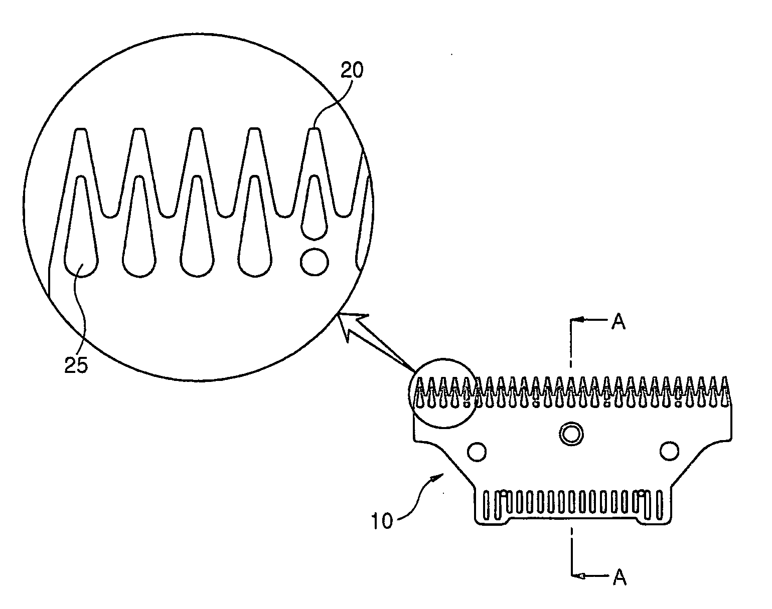
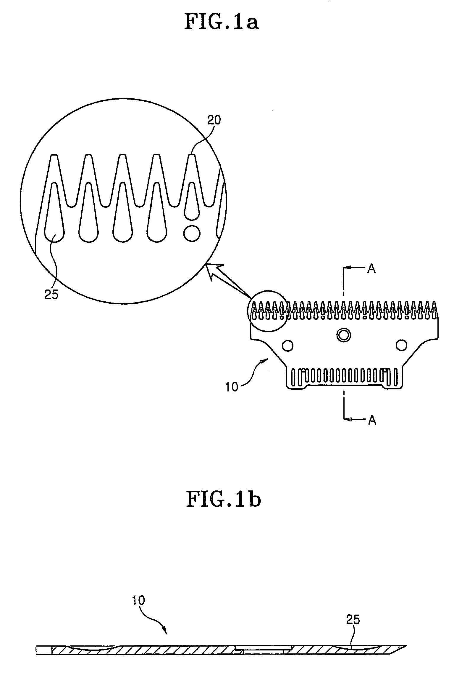
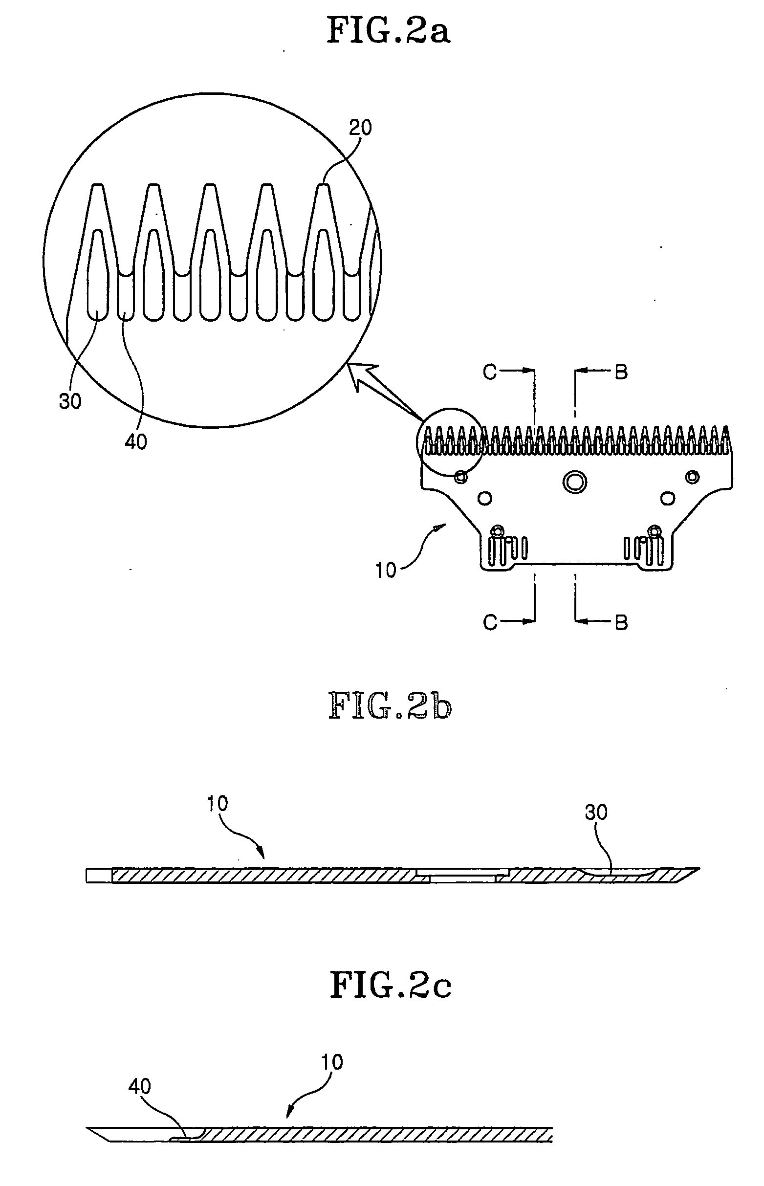
[0013]FIG. 2a is a bottom view illustrating a movable blade for use in an electric hair clipper in accordance with the present invention, and FIGS. 2b and 2c are sectional views taken along the line B-B and the line C-C shown in FIG. 2a, respectively. FIG. 3 is a sectional view illustrating an assembled shape of the movable blade and a stationary blade of the electric hair clipper in accordance with the present invention.

[0014] As shown in FIG. 2a, the movable blade 10 of the electric hair clipper comprises a plurality of etched blade teeth 20 arranged in a row along a tip end thereof, a plurality of first etched recesses 30 centrally formed at the etched blade teeth 20 in a one to one ...


PUM


Abstract

Disclosed herein is an etched movable blade for use in an electric hair clipper. The electric hair clipper comprises a stationary blade in addition to the movable blade, and the movable blade is displaceably disposed on an upper surface of the stationary blade so as to perform hair cutting by making use of a plurality of etched blade teeth formed at tip ends of the movable and stationary blades. The movable blade comprises a plurality of etched recesses formed, respectively, between adjacent ones of the etched blade teeth, thereby achieving an increase in a surface area of etched portions compared to a conventional etched blade, and effectively preventing the accumulation of hair or residue between the stationary blade and the movable blade, resulting in enhancement in cutting efficiency of the electric hair clipper.

Description

TECHNICAL FIELD [0001] The present invention relates to an etched blade of electric hair clippers, and more particularly to an etched movable blade for use in an electric hair clipper, which is displaceably disposed on the upper surface of a stationary blade of the electric hair clipper, and comprises a plurality of etched recesses, positioned, respectively, between adjacent ones of plural etched blade teeth separated by spaces, thereby preventing the accumulation of hair or residue between the stationary blade and the movable blade. BACKGROUND ART [0002] Referring to FIG. 1 illustrating a conventional movable blade for use in an existing electric hair clipper and to FIG. 1b shown as a sectional view taken along the line A-A of FIG. 1a, the movable blade, designated as reference numeral 10, is formed, along a tip end of one surface thereof, with a plurality of recesses 25, by etching. These etched recesses 25, however, are insufficient to prevent the accumulation of hair or residue ...

Claims


Application Information

Patent Timeline
IPC IPC(8): B26B19/02B26B19/06B26B19/38
CPCB26B19/3846B26B19/04
Inventor O, TAE-JUN
Owner O TAE JUN
Why Eureka
Try Eureka