Container-fabricating apparatus and a method for the cleaning thereof

Active Publication Date: 2016-06-16
DISCMA
View PDF2 Cites 3 Cited by
  • Summary
  • Abstract
  • Description
  • Claims
  • Application Information

AI Technical Summary

Benefits of technology

The invention provides a device for cleaning and sterilizing a stretching rod used in a manufacturing process. The device has a cleaning chamber that can envelope the stretching rod, allowing for easy and quick cleaning. The use of steam as a cleaning fluid ensures that the surface of the injection head is sterilized, improving the sanitary conditions and preventing contamination during the injection process.

Problems solved by technology

This is problematic, in that cleaning, and maintaining the cleanliness of, the molding apparatuses known in the art is difficult.
Cleaning the stretching rod is difficult, in that it requires one to halt the production of containers and extend the stretching rod from the injection head so that it may be cleaned.

Method used


Image

  • Container-fabricating apparatus and a method for the cleaning thereof
  • Container-fabricating apparatus and a method for the cleaning thereof
  • Container-fabricating apparatus and a method for the cleaning thereof

Examples


first embodiment

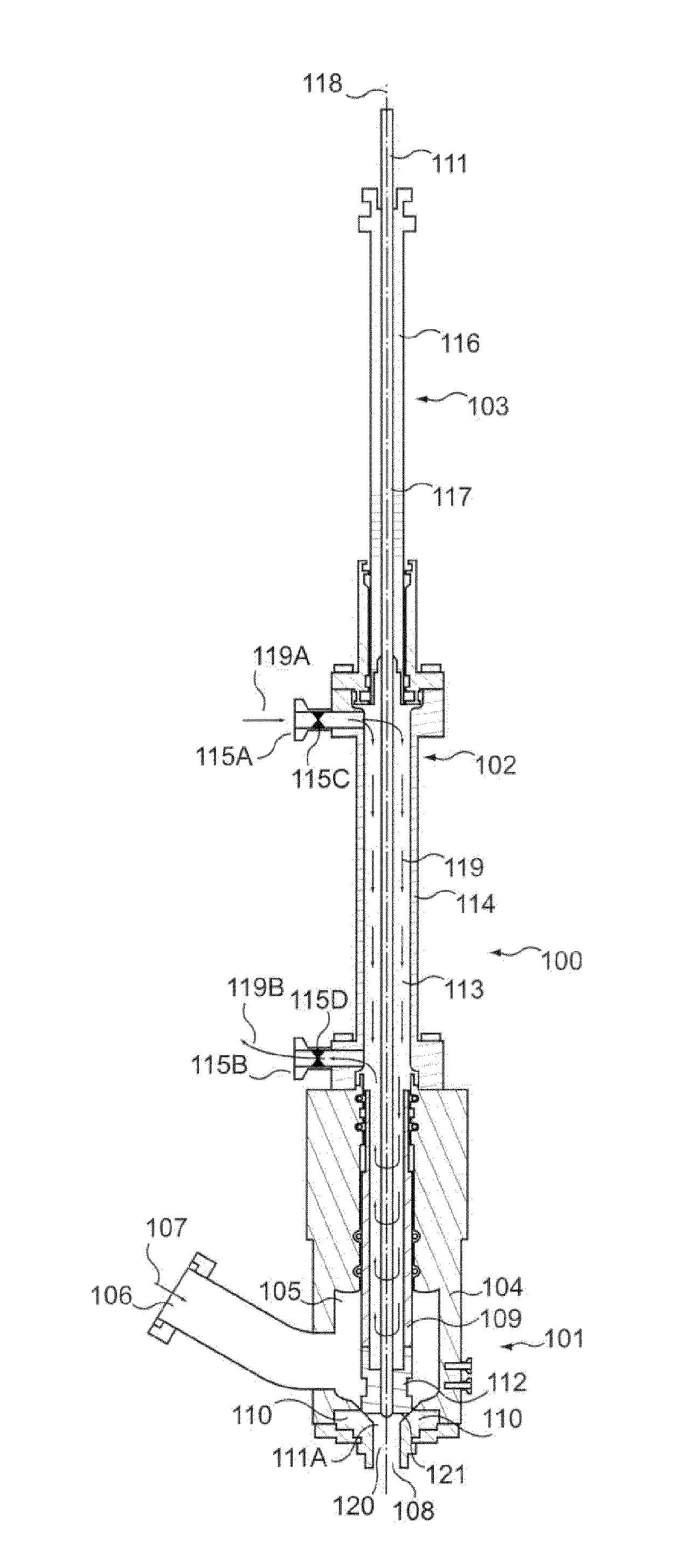
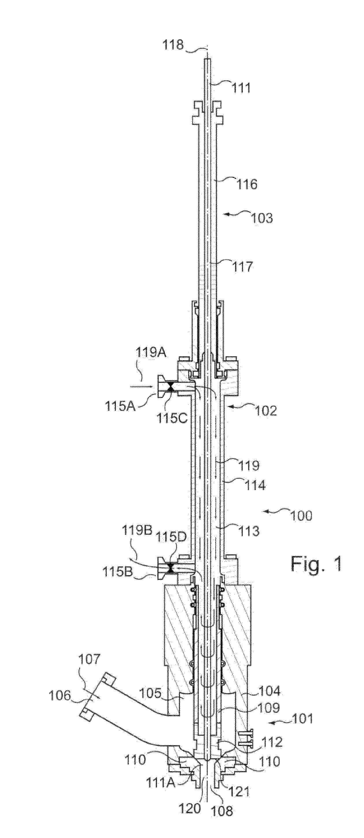
[0065]FIG. 1 is a side section view of an injection apparatus 100 according to the invention. The injection apparatus 100 globally comprises three sections: an injection head section 101, a cleaning chamber section 102, and a guide section 103. The construction, operation, and interaction of these three sections will be discussed.

[0066]The injection head section 101 is globally configured to engage with a preform (not shown) which is expanded into a container during normal operation of the injection apparatus 100. The injection head section 101 is comprised of the valve body 104, which is substantially hollow and thus defines the valve chamber 105. The valve body 104 is furnished with an injection fluid port 106, which communicates with the valve chamber 105. In ordinary operation, the injection liquid 107 is introduced into the valve chamber 105 through the injection fluid port 106.

[0067]The valve chamber 105 is further provided with a nozzle 108, which is configured to engage with...

second embodiment

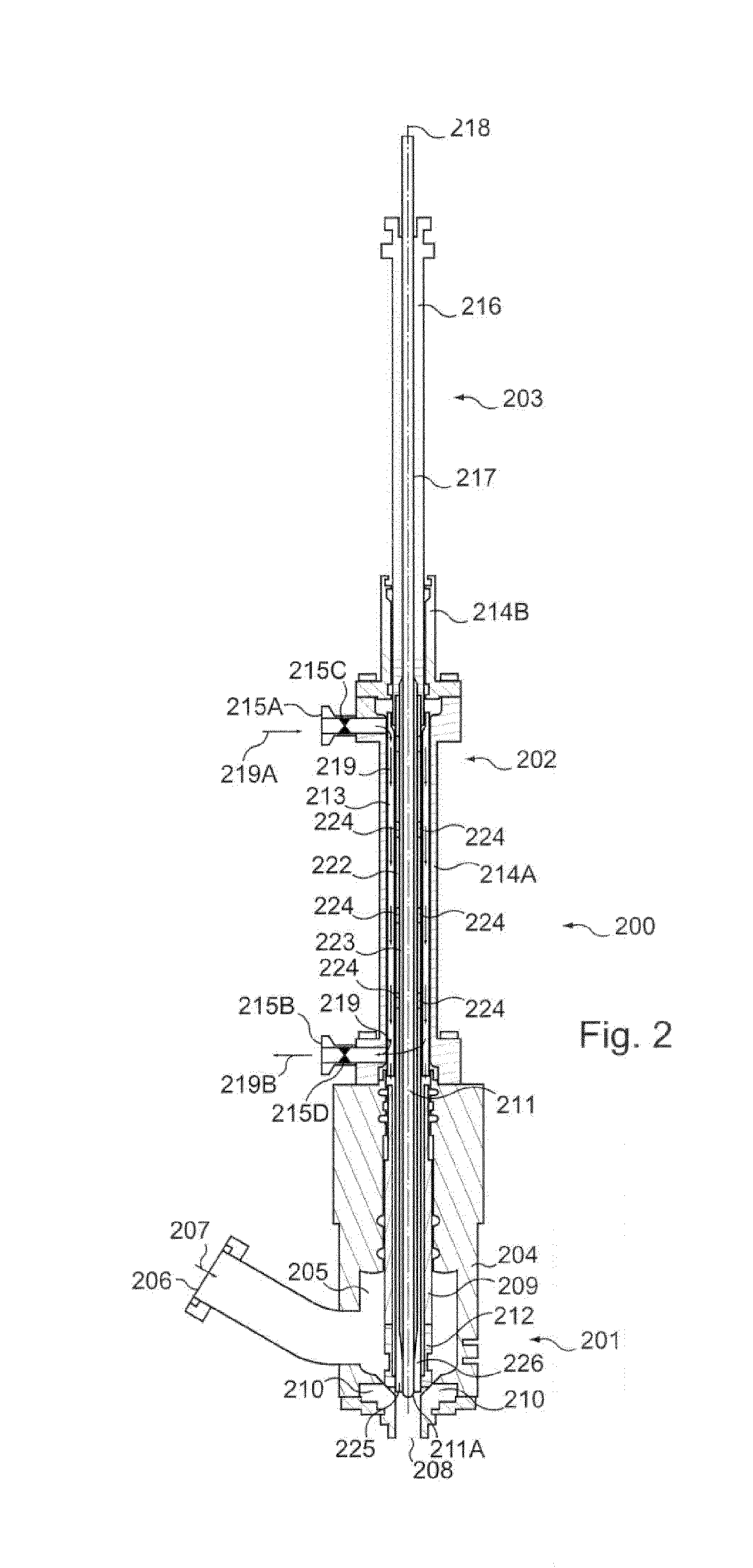
[0088]FIG. 2 depicts an injection apparatus 200 according to the invention. The injection apparatus 200 is broadly constructed in the same way as the injection apparatus 100 of FIG. 1, comprising an injection head section 201, a cleaning chamber section 202, and a guide section 203.

[0089]As in the previous embodiment, the injection head section 201 is globally configured to engage with a preform (not shown) at the nozzle 208, so as to ultimately expand the preform into a container. The injection head section 201 is primarily comprised of the valve body 204 which defines the valve chamber 205. The valve body 204 is furnished with an injection fluid port 206, which communicates with the valve chamber 205. During the fabrication of a container, the injection liquid 207 is introduced into the valve chamber 205 through the injection fluid port 206.

[0090]Within the valve chamber 205 is the injection valve 209, there is provided the injection valve 209 which seats against the valve seats 2...


PUM

PropertyMeasurementUnit
Lengthaaaaaaaaaa
Diameteraaaaaaaaaa
Lengthaaaaaaaaaa

Abstract

A container-fabricating apparatus having an injection head establishing fluid communication between an injection fluid port disposed therein and a preform disposed in communication with a nozzle of the injection head. The apparatus also including a stretching rod moveable between a position projecting from the injection head through the nozzle and a substantially retracted position. The apparatus further includes a cleaning chamber at least partially defined by a hollow, elongate housing contiguous with and extending from the injection head, a plurality of cleaning chamber ports in a wall of the housing establishing fluid communication with the cleaning chamber, the stretching rod being substantially disposed within the cleaning chamber when disposed in the substantially retracted position.

Description

CROSS-REFERENCE TO RELATED APPLICATIONS[0001]This application is the U.S. national phase of PCT Application No. PCT / EP2014 / 063940 filed on Jul. 1, 2014, which claims priority to EP13174788.3 filed on Jul. 2, 2013, the disclosures of which are incorporated in their entirety by reference herein.TECHNICAL FIELD[0002]The invention relates to a container-fabricating apparatus. Specifically, the invention relates to such an apparatus as provided with a means for facilitating the cleaning thereof. The invention further relates to a method for cleaning an apparatus so configured.BACKGROUND OF THE INVENTION[0003]It is generally well known in the art to fabricate containers by the process of blow molding, wherein a plastic parison known as a “preform” is molded into a container. This preform is generally provided in the form of an elongated tube which defines a preform cavity and which is provided with a closed distal end and a mouth at an open proximal end in communication with the preform c...

Claims


Application Information

Patent Timeline
IPC IPC(8): B29C33/72B29C49/12B29C49/46B29C49/58
CPCB29C33/72B29C49/58B29C2049/4694B29C49/46B29C49/12B29C49/4289B29C2049/465B29C2049/5817B29C49/1232B29C49/42403
Inventor CHAUVIN, GUILLAUMECOLLIN, CHRISTOPHEKANNENGIESSER, DAMIENOUTREMAN, JEAN-TRISTANPELLEGATTA, JEAN-LOUIS
Owner DISCMA
Why Eureka
Try Eureka