Downhole safety valve

a safety valve and downhole technology, applied in the field of safety valves, can solve the problems of mechanical bias, insufficient pressure on the first piston surface, etc., and achieve the effect of preventing sudden pressure loss

Inactive Publication Date: 2006-07-20
WEATHERFORD TECH HLDG LLC
View PDF33 Cites 21 Cited by
  • Summary
  • Abstract
  • Description
  • Claims
  • Application Information

AI Technical Summary

Benefits of technology

[0012] The present invention generally provides a method and apparatus for selectively sealing a bore. The tubular valve generally includes a closing member for seating in and closing the bore, and a pressure-actuated, retention member having first and second opposed piston surfaces opening and closing the valve. The tubular valve prevents sudden loss of pressure in the tubular and is controllable from the surface.

Problems solved by technology

The method further includes applying a wellbore pressure to the first piston surface and increasing the pressure in the pressure chamber to a level sufficient to overcome the mechanical bias of the retention member, but insufficient to overcome both the pressure on the first piston surface and the mechanical bias.

Method used


Image

  • Downhole safety valve
  • Downhole safety valve
  • Downhole safety valve

Examples


Embodiment Construction

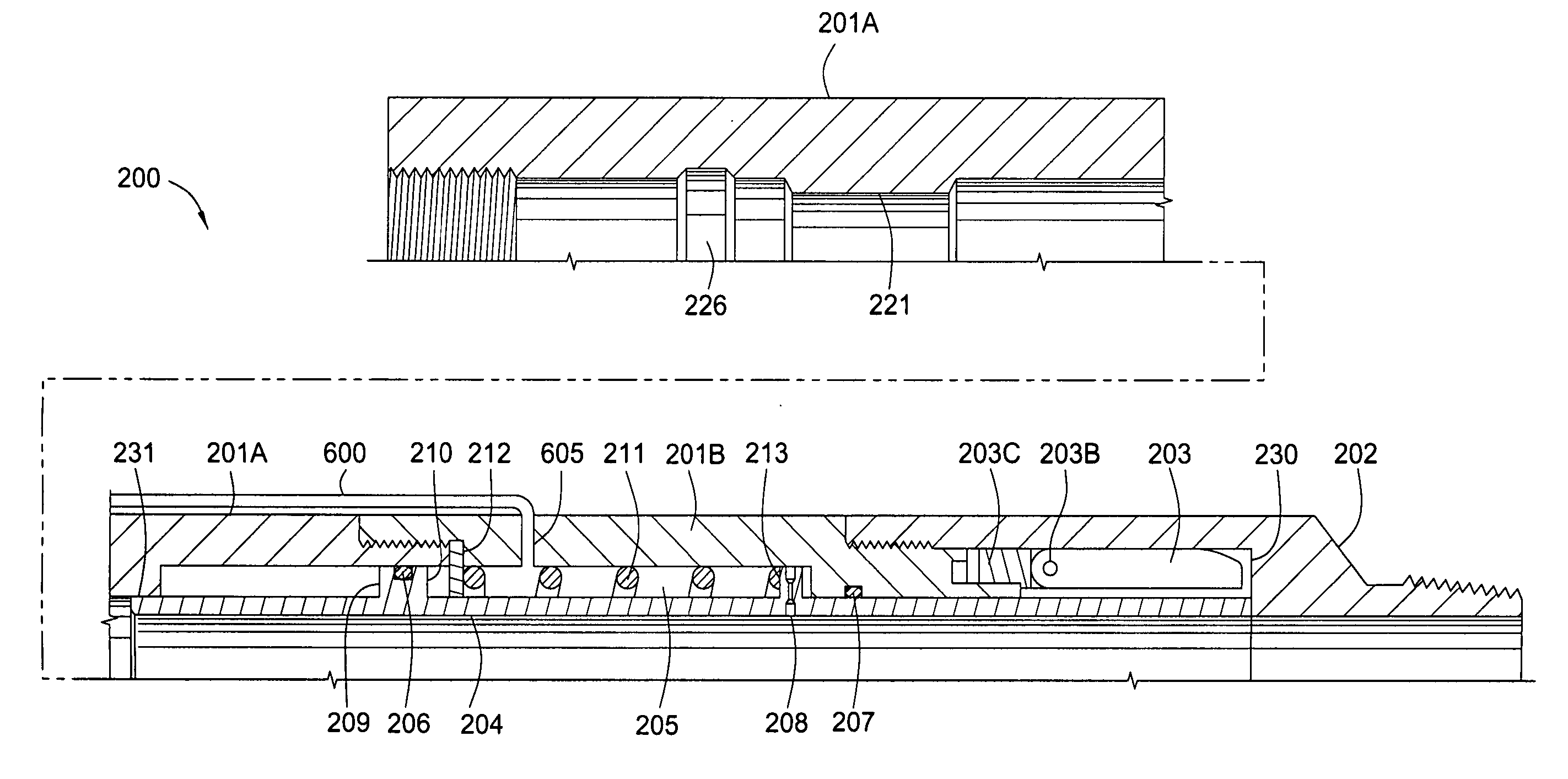
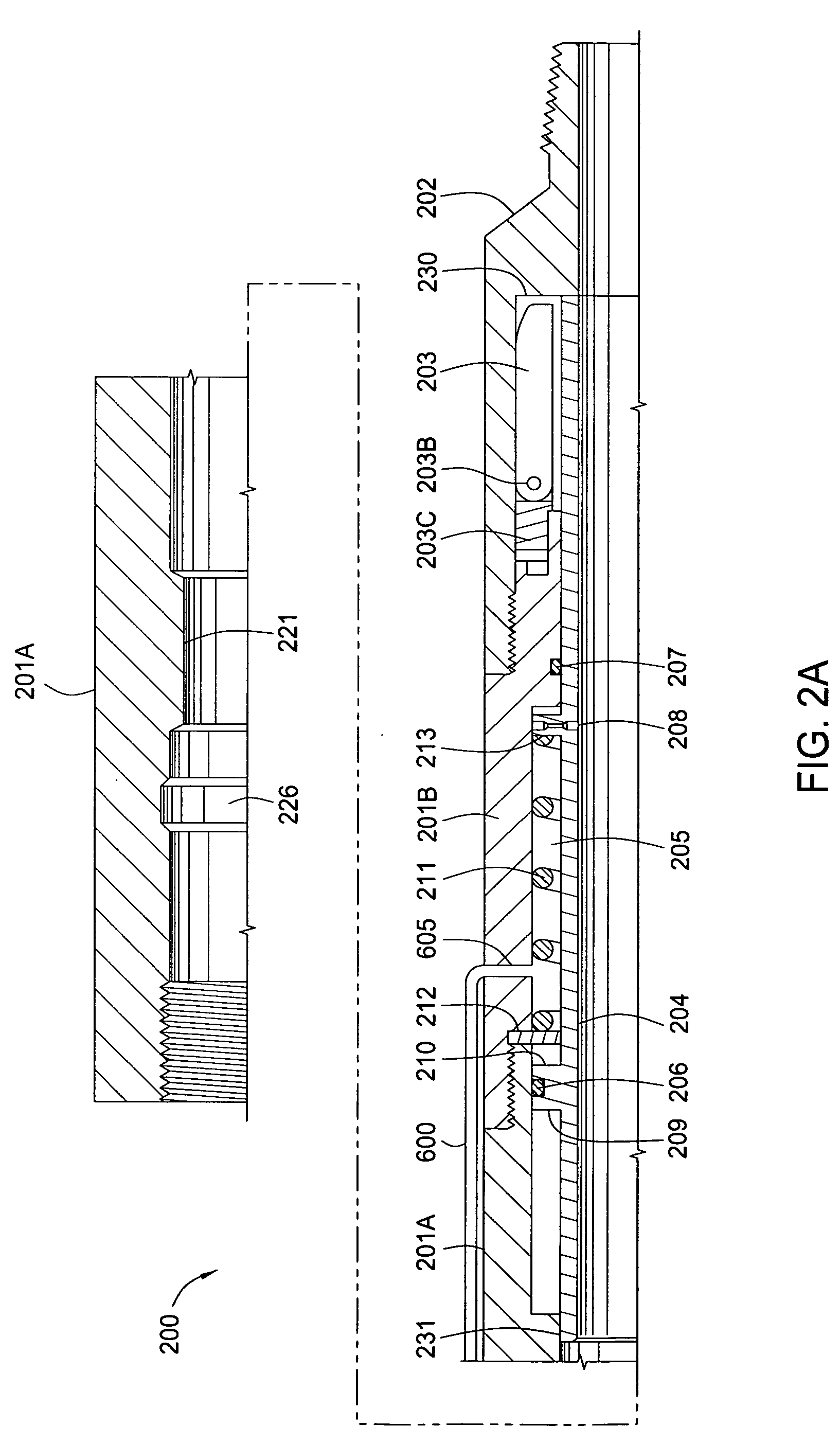
[0024] The apparatus and methods of the present invention allow for a safety valve for subsurface wells. Embodiments of the present invention provide safety valves that utilize normal wellbore pressure for actuation of the valve, which removes the need for hydraulic systems with control lines extending from the surface to the valve, however, a control system is incorporated into the invention for further control of the valve.

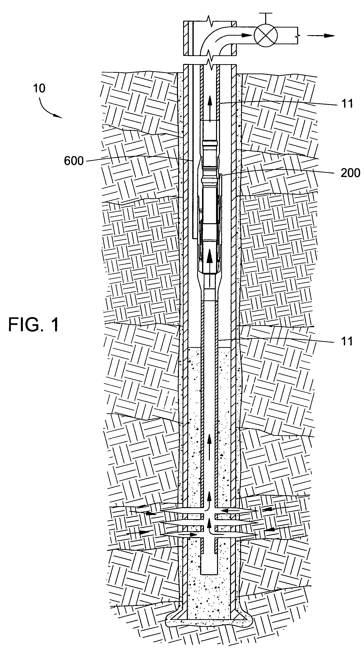
[0025]FIG. 1 is a cross-sectional view of an illustrative wellbore 10. The wellbore is completed with a string of production tubing 11. The production tubing 11 defines an elongated bore through which servicing fluid may be pumped downward and production fluid may be pumped upward. The production tubing 11 includes a safety valve 200 in accordance with one embodiment of the present invention. The safety valve 200 controls the upward flow of production fluid through the production tubing 11 in the event of a sudden and unexpected pressure loss (also referred to ...


PUM


Abstract

The present invention generally provides a method and apparatus for selectively sealing a bore. The tubular valve generally includes a closing member for seating in and closing the bore, and a pressure-actuated, retention member having first and second opposed piston surfaces opening and closing the valve. The tubular valve prevents sudden loss of pressure in the tubular and is controllable from the surface.

Description

CROSS-REFERENCE TO RELATED APPLICATIONS [0001] This application is a continuation-in-part of co-pending U.S. patent application Ser. No. 10 / 957,240 filed Oct. 1, 2004. Further, this application claims benefit of U.S. provisional patent application Ser. No. 60 / 664,487 filed Mar. 23, 2005, which is herein incorporated by reference. Each of the aforementioned related patent applications are herein incorporated by reference.BACKGROUND OF THE INVENTION [0002] 1. Field of the Invention [0003] Embodiments of the present invention generally relate to safety valves. More particularly, embodiments of the present invention pertain to subsurface safety valves configured to actuate using wellbore pressure in the event of an unexpected pressure drop. More particularly still, embodiments of the present invention pertain to the further ability to control the safety valves from the surface. [0004] 2. Description of the Related Art [0005] Subsurface safety valves are commonly used to shut-in oil and ...

Claims


Application Information

Patent Timeline
Patent Type & Authority Applications(United States)
IPC IPC(8): E21B34/10E21B34/00
CPCE21B34/10E21B2034/005E21B2200/05E21B34/08
Inventor SMITH, RODDIE R.
Owner WEATHERFORD TECH HLDG LLC
Why Eureka
Try Eureka