Saw blade

Inactive Publication Date: 2006-07-27
AMADA CO LTD
View PDF10 Cites 38 Cited by
  • Summary
  • Abstract
  • Description
  • Claims
  • Application Information

AI Technical Summary

Benefits of technology

[0019] Consequently, it is possible to suppress a vertical dimension to a low level in view of a horizontal abrasion quantity at t

Problems solved by technology

As a consequence, the saw blade 101 is turned into an unstable state, thereby inducing breakage or bending.
In this case, since a fine portion in the vicinity of the tip of the cutting tooth in the saw blade 101 is deformed in the lateral direction with application of lateral large force, the tip of the cutting tooth

Method used


Image

  • Saw blade
  • Saw blade
  • Saw blade

Examples


Embodiment Construction

[0030] A description will be given below of saw blades in preferred embodiments according to the invention in reference to the attached drawings.

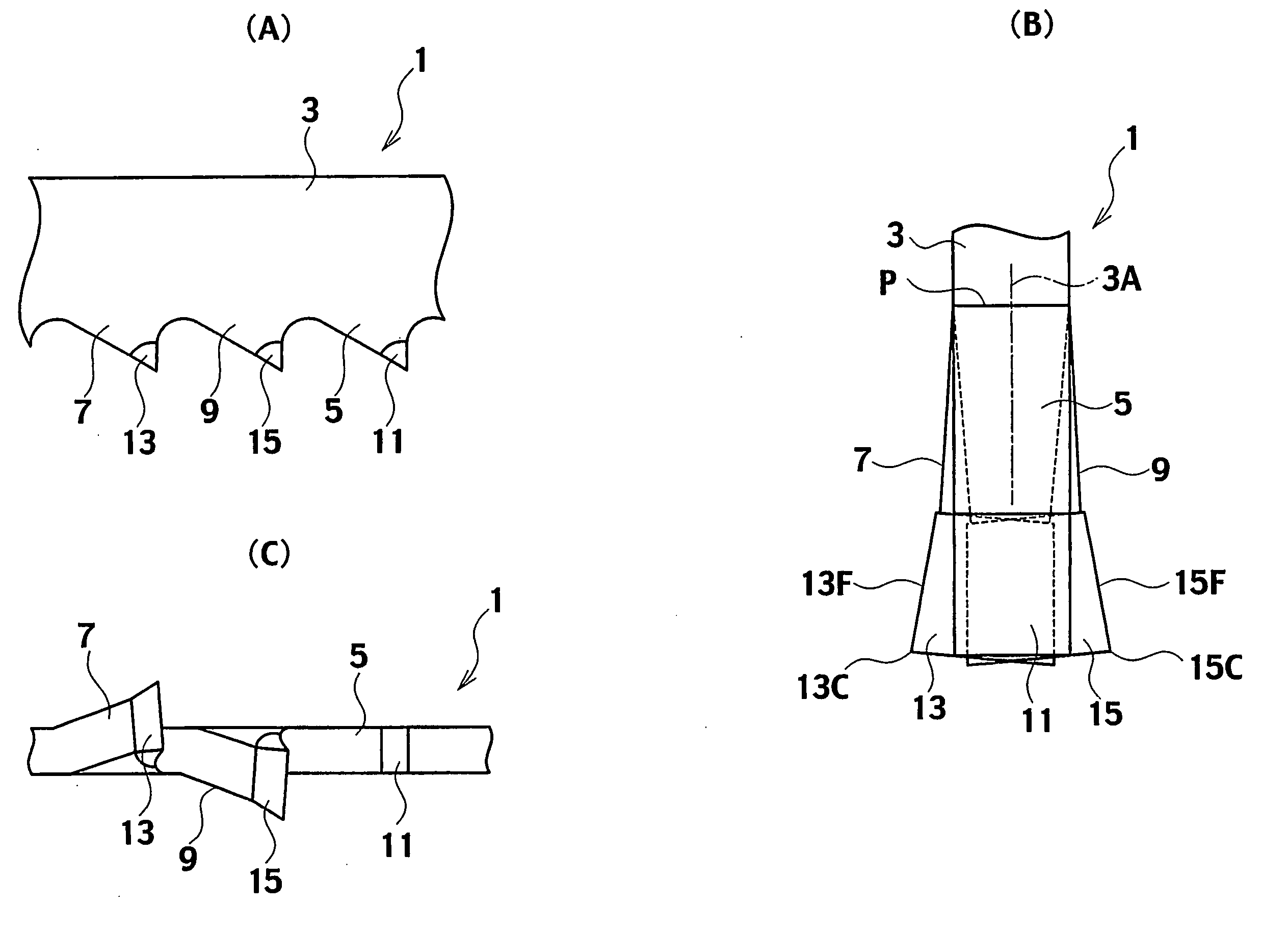
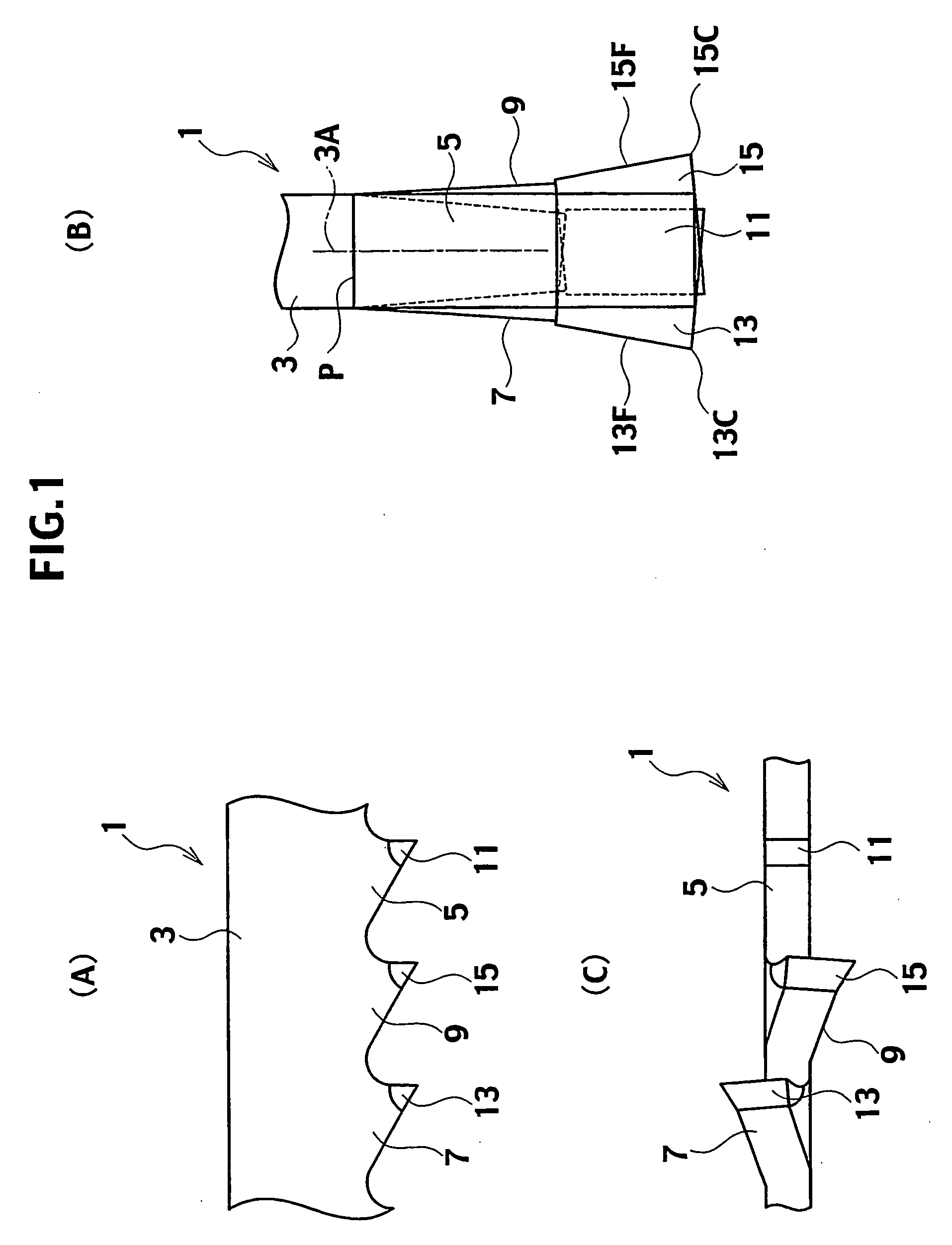
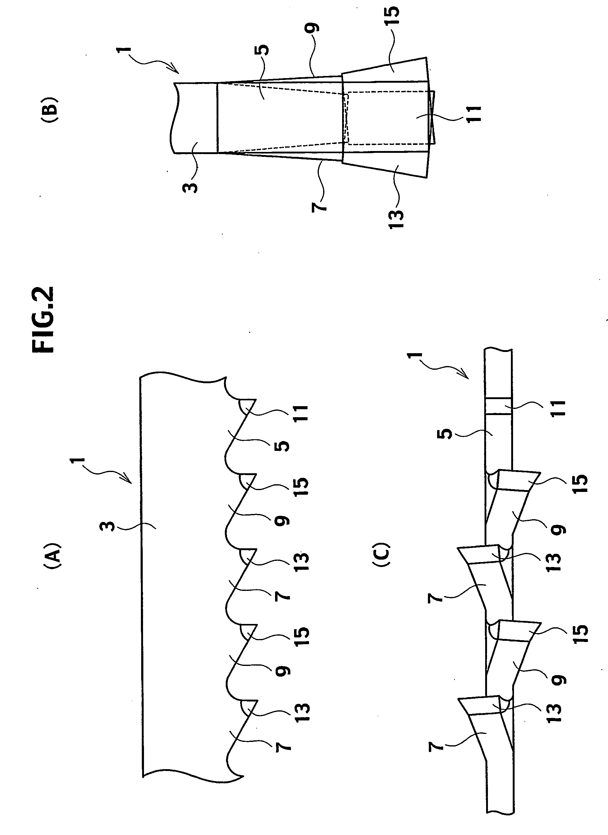
[0031] Referring to FIGS. 1A to 1C, a saw blade 1 in a first preferred embodiment according to the invention includes a blade base 3 made of a highly resilient material such as a spring steel. At the blade base 3 are formed numerous cutting teeth for cutting a workpiece (which is not shown in FIGS. 1A to 1C) at appropriate pitches. The cutting teeth include a straight tooth 5, which precedes in a cutting direction (i.e., rightward in FIG. 1A) in cutting the workpiece, serving as a preceding tooth, and further, left and right set teeth 7 and 9 serving as subsequent teeth, which are subsequent to the straight tooth 5.

[0032] The straight tooth 5 is a straight saw tooth, which is not set in a lateral direction, as viewed in the cutting direction of the saw blade 1 with respect to the workpiece. In contrast, the left and right set teeth 7 and ...


PUM

PropertyMeasurementUnit
Thicknessaaaaaaaaaa
Heightaaaaaaaaaa

Abstract

A saw blade includes left and right set teeth which are set in a lateral direction, as viewed in a cutting direction of cutting teeth. The left and right set teeth include dovetail shaped set teeth, each having a tooth tip formed into a dovetail shape gradually enlarged in the lateral direction, respectively; and a straight tooth, which is not set. The straight tooth includes a dovetail shaped straight tooth having a tooth tip formed into a dovetail shape gradually enlarged in the lateral direction. In the straight tooth, inclinations are formed on both of left and right ends at the tooth tip, which is formed into the dovetail shape gradually enlarged in the lateral direction.

Description

TECHNICAL FIELD [0001] The present invention relates to a saw blade and, more particularly, to a saw blade including a dovetail shaped set tooth having left and right set teeth, which are set on left and right sides and whose tooth tips are formed into a dovetail shape gradually enlarged in a lateral direction. BACKGROUND ART [0002] In conventional manner, in the case where a metallic workpiece, for example, is cut, saws such as a circular saw and a band saw have been widely used in the prior art. A saw blade serving as a cutting tool for use in the above-described saw is configured such that numerous cutting teeth for cutting the workpiece are arranged at appropriate pitches. Exemplary types of saw blades include a so-called set tooth type and a dovetail shaped set tooth type. [0003] The above-described set tooth is provided with a straight tooth, as viewed in a cutting direction of the cutting teeth, and left and right set teeth whose tooth tips are set in a lateral direction in o...

Claims


Application Information

Patent Timeline
IPC IPC(8): B23D57/00B23D61/12
CPCB23D61/121Y10T83/9319Y10T83/9346Y10T83/935
Inventor NAGANO, YUJIKAMIYAMA, IWAO
Owner AMADA CO LTD
Why Eureka
Try Eureka