Guiding movement of capless filler neck closure

a technology of filler neck and guide rod, which is applied in the direction of liquid handling, refuse gathering, packaging goods type, etc., can solve the problems that the filler cap has proven to be a source of trouble, and achieve the effect of eliminating scrubbing and facilitating a positive seal

Inactive Publication Date: 2006-07-27
EATON CORP
View PDF9 Cites 11 Cited by
  • Summary
  • Abstract
  • Description
  • Claims
  • Application Information

AI Technical Summary

Benefits of technology

This patent describes an improved design for a capless fuel tank that uses a flexible membrane instead of a traditional lid. A closable door sits atop the opening of the fuel tank, allowing it to easily open when a new fuel nozzle is inserted. When the nozzle is removed, the door automatically reverses its motion to ensure a tight seal without any leaks. Overall, this design helps prevent damage to the fuel tank while still providing easy access for refueling operations.

Problems solved by technology

The technical problem addressed in this patent is how to design a secure and reliable closure for the refueling nozzle opening of a fuel tank filler neck that allows for efficient refueling while preventing leaks caused by poorly fitting or worn out filler caps. Additionally, the closure should allow for accurate detection and monitoring of fuel system integrity through periodic on-board diagnostic tests without interfering with the driver's ability to operate the car safely.

Method used


Image

  • Guiding movement of capless filler neck closure
  • Guiding movement of capless filler neck closure
  • Guiding movement of capless filler neck closure

Examples


Embodiment Construction

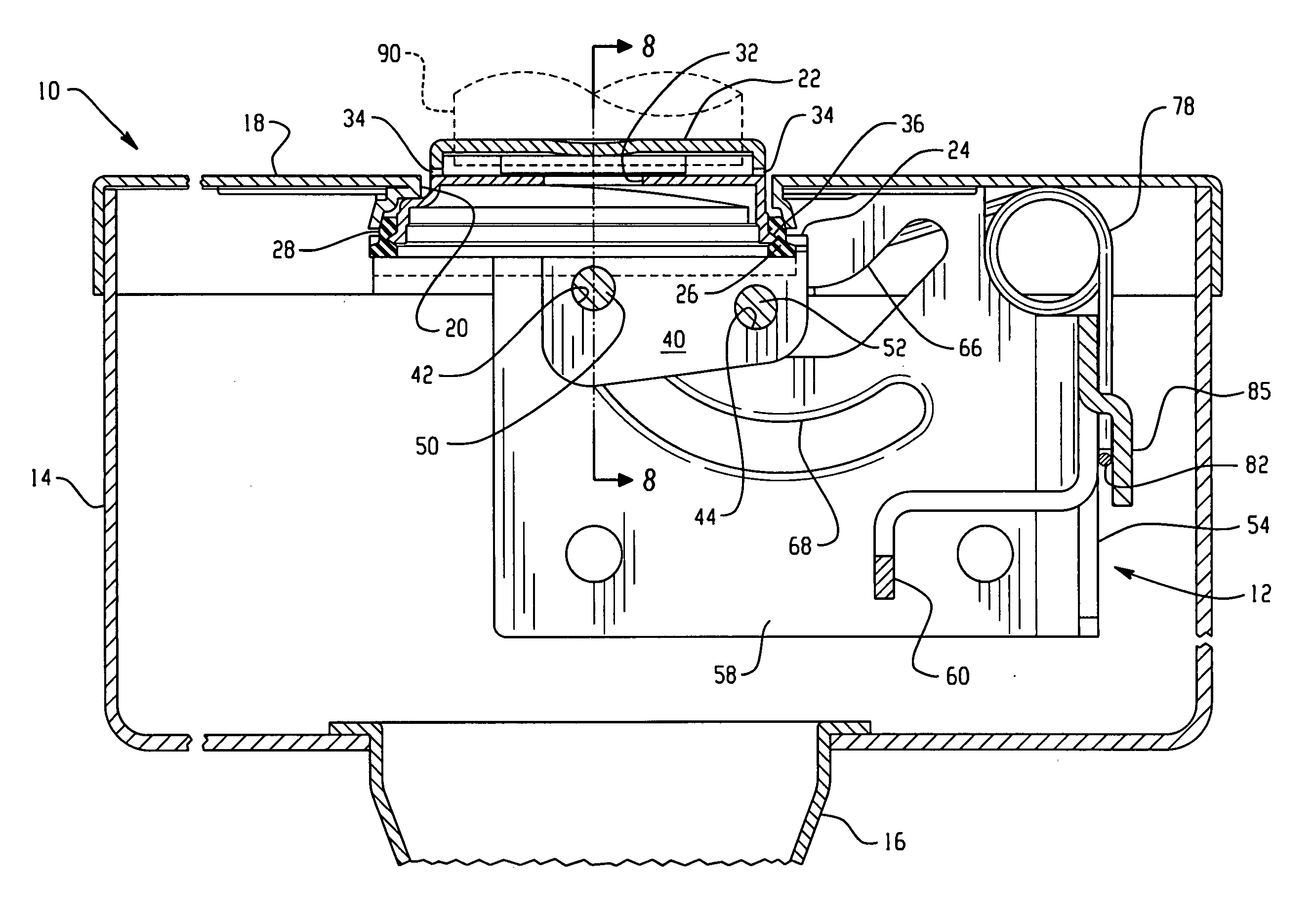
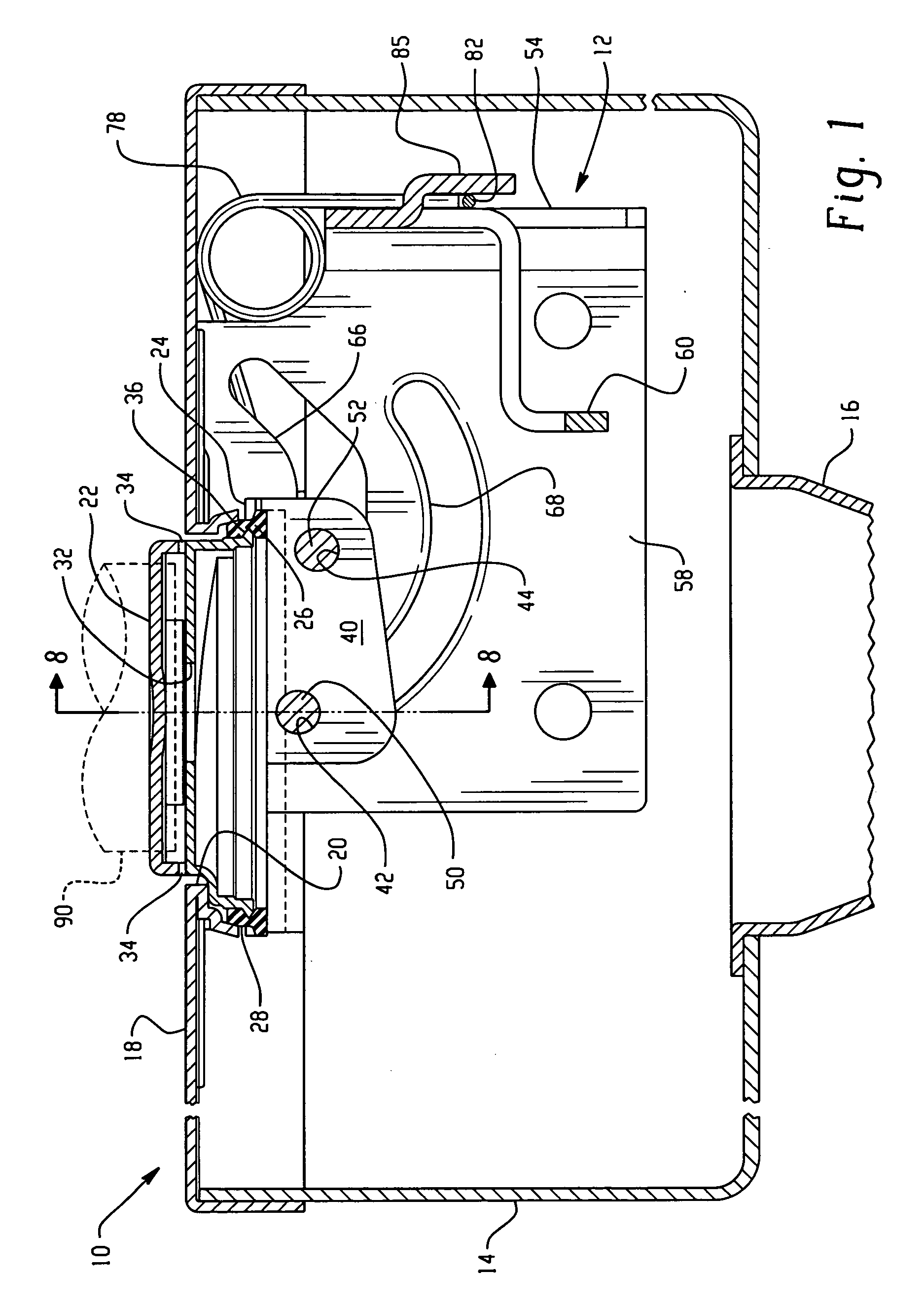
[0015] Referring to FIG. 1, a fuel tank filler tube assembly embodying the present invention is indicated generally at 10 wherein a capless closure and support structure are indicated as a subassembly generally at 12 as received in a filler cup 14 attached to the upper end of the filler tube or neck 16. The filler cup 14 has a bulkhead 18 secured and sealed over the open end thereof, which bulkhead has a nozzle-receiving aperture 20 formed therein.

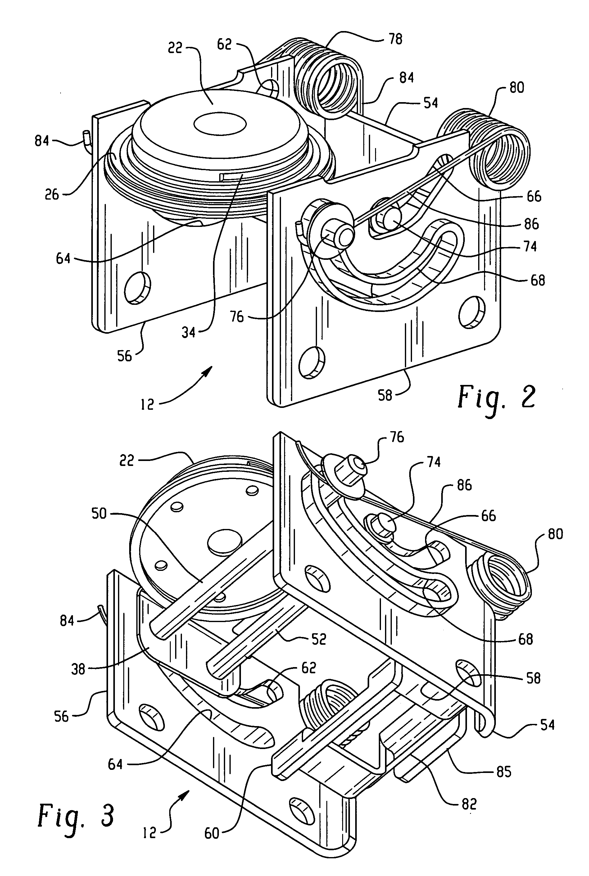
[0016] In the illustrated exemplary embodiment a closure door 22 is shown with a radially outwardly extending peripheral flange 24 formed thereon which has a plurality of apertures 28 therethrough which may be spaced circumferentially thereabout. A flexible annular seal 26 is disposed about the flange and secured thereto; as, for example, by insert molding the seal 26 thereon with portions of the molded seal material passing through the apertures 28. The door 22 may include a one-way pressure relief valve (not shown) which opens to permit...


PUM

PropertyMeasurementUnit
Flexibilityaaaaaaaaaa

Abstract

A capless filler tube closure door has a pair of spaced axles or pins which are guided by slots to initially upon being opened by a refueling nozzle move in translation away from the nozzle orifice seat and then pivot out of the way so as not to obstruct the nozzle. Upon nozzle removal as the door approaches the seat, it moves in linear translation to close on the seat to ensure uniform sealing.

Description


Claims


Application Information

Patent Timeline
Owner EATON CORP
Why Eureka
Try Eureka