Protective sleeve for threaded connections for expandable liner hanger

a protective sleeve and expandable technology, applied in the field of oil and gas exploration, can solve the problems of inability to reliably and satisfactorily produce satisfactory results, inability to radially expand and plastically deform tubular members coupled to one another by threaded connections, and damage to threaded connections between adjacent tubular members, whether radially expanded or deformed

Inactive Publication Date: 2006-07-27
ENVENTURE GLOBAL TECH LLC
View PDF99 Cites 44 Cited by
  • Summary
  • Abstract
  • Description
  • Claims
  • Application Information

AI Technical Summary

Problems solved by technology

Existing methods for radially expanding and plastically deforming tubular members coupled to one another by threaded connections are not always reliable or produce satisfactory results.
In particular, the threaded connections can be damaged during the radial expansion process.
Furthermore, the threaded connections between adjacent tubular members, whether radially expanded or not, are typically not sufficiently coupled to permit the transmission of energy through the tubular members from the surface to a downhole location.

Method used


Image

  • Protective sleeve for threaded connections for expandable liner hanger
  • Protective sleeve for threaded connections for expandable liner hanger
  • Protective sleeve for threaded connections for expandable liner hanger

Examples


Embodiment Construction

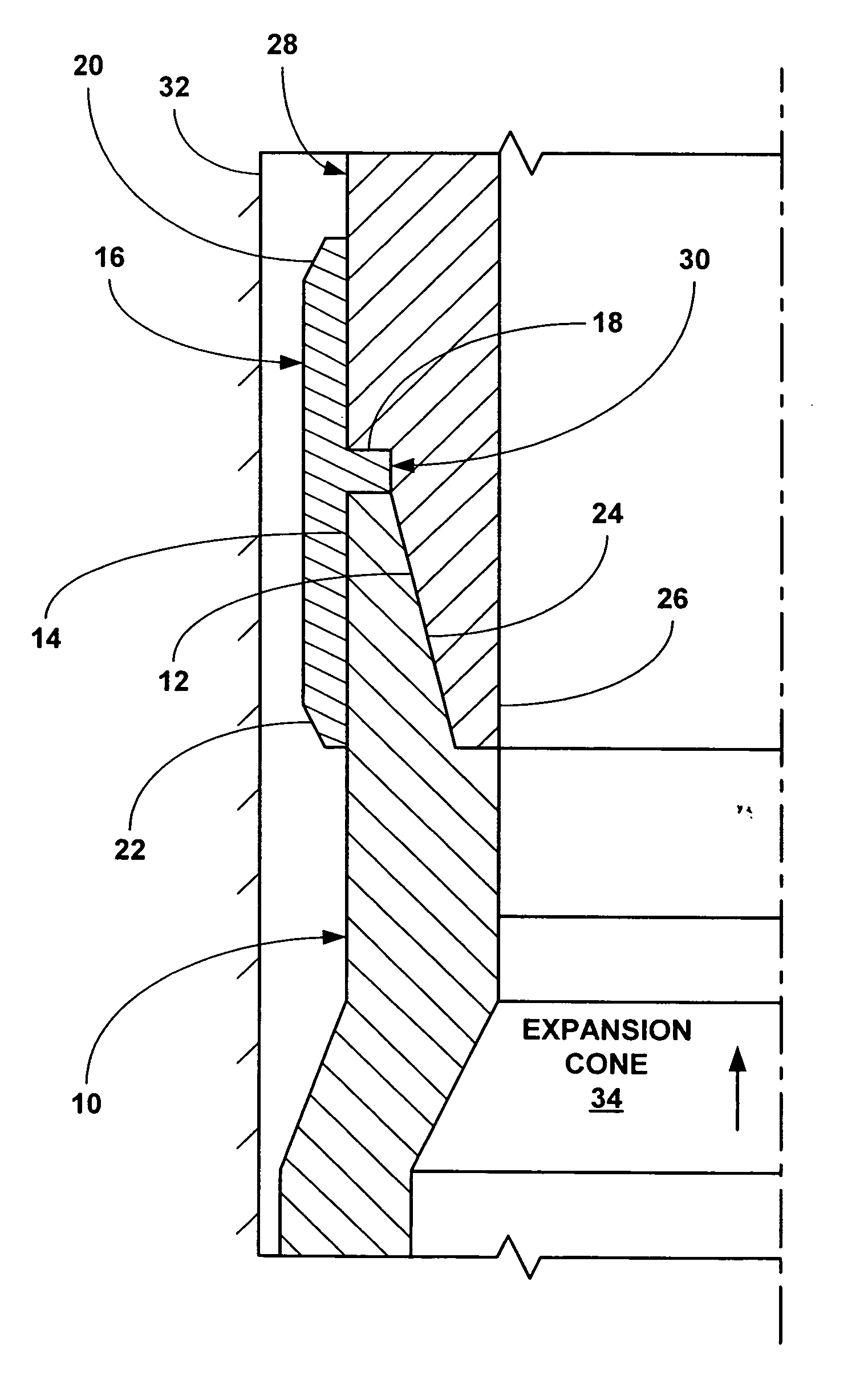
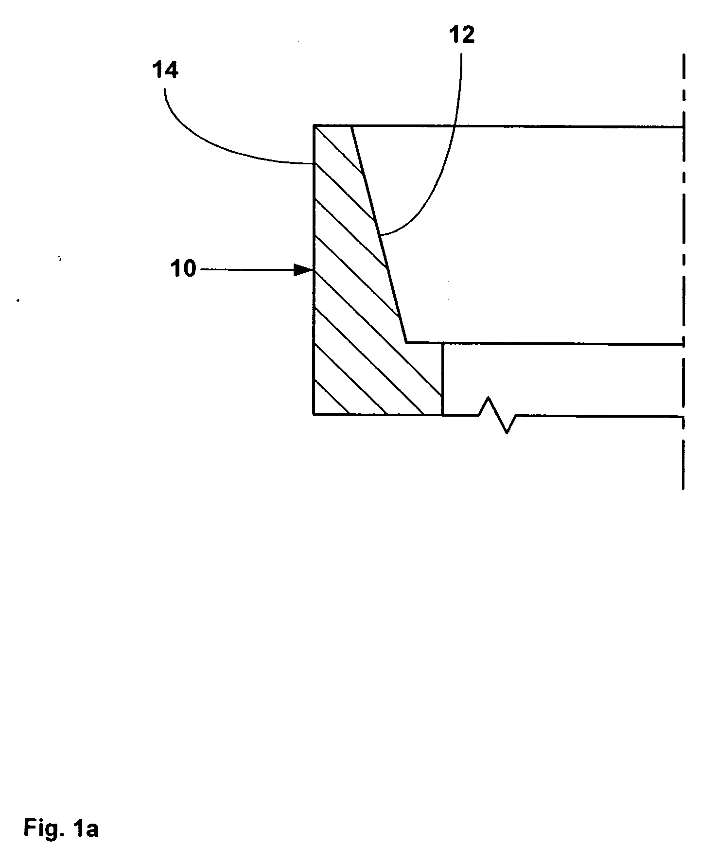
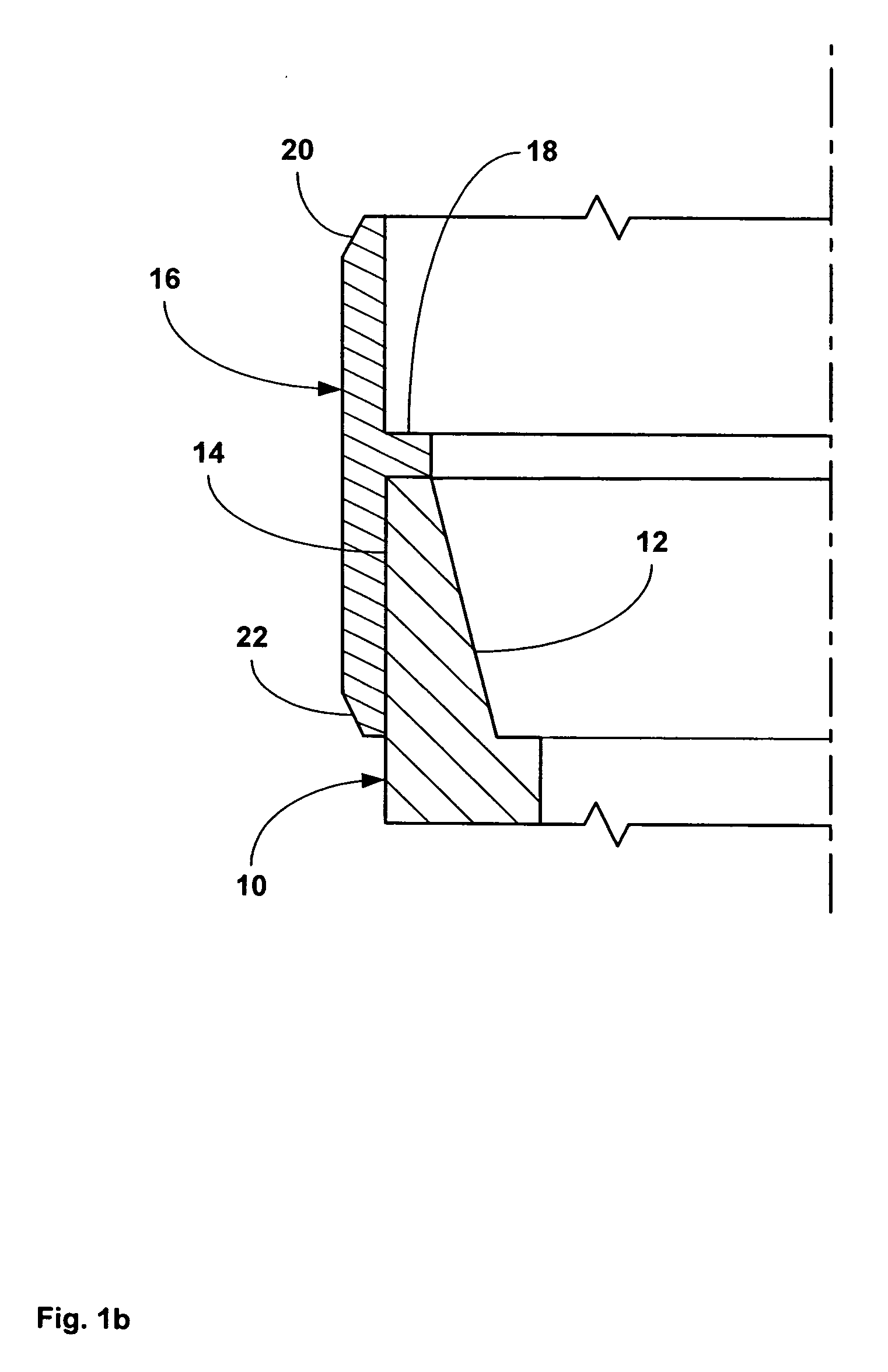
[0084] Referring to FIG. 1a, a first tubular member 10 includes an internally threaded connection 12 at an end portion 14. As illustrated in FIG. 1b, a first end of a tubular sleeve 16 that includes an internal flange 18 and tapered portions, 20 and 22, at opposite ends is then mounted upon and receives the end portion 14 of the first tubular member 10. In an exemplary embodiment, the end portion 14 of the first tubular member 10 abuts one side of the internal flange 18 of the tubular sleeve 16, and the internal diameter of the internal flange of the tubular sleeve is substantially equal to or greater than the maximum internal diameter of the internally threaded connection 12 of the end portion of the first tubular member. As illustrated in FIG. 1c, an externally threaded connection 24 of an end portion 26 of a second tubular member 28 having an annular recess 30 is then positioned within the tubular sleeve 16 and threadably coupled to the internally threaded connection 12 of the en...


PUM


Abstract

A tubular sleeve is coupled to and overlaps the threaded connection between a pair of adjacent tubular members.

Description

CROSS REFERENCE TO RELATED APPLICATIONS [0001] The present application claims the benefit of the filing dates of (1) U.S. provisional patent application Ser. No. 60 / 397,284, attorney docket no 25791.106, filed on Jul. 19, 2002, which is a continuation-in-part of U.S. provisional patent application Ser. No. 60 / 372,632, attorney docket no. 25791.101, filed on Apr. 15, 2002, which was a continuation-in-part of U.S. provisional patent application Ser. No. 60 / 372,048, attorney docket no. 25791.93, filed on Apr. 12, 2002, which was a continuation-in-part of U.S. provisional patent application Ser. No. 60 / 346,309, attorney docket no. 25791.92, filed on Jan. 7, 2002, the disclosures of which are incorporated herein by reference. [0002] The present application is related to the following: (1) U.S. patent application Ser. No. 09 / 454,139, attorney docket no. 25791.03.02, filed on Dec. 3, 1999, (2) U.S. patent application Ser. No. 09 / 510,913, attorney docket no. 25791.7.02, filed on Feb. 23, 20...

Claims


Application Information

Patent Timeline
Patent Type & Authority Applications(United States)
IPC IPC(8): E21B17/02E21B23/00E21B17/042E21B17/10E21B43/10
CPCE21B17/042E21B17/1085E21B43/103E21B43/106E21B17/04E21B17/08E21B47/117
Inventor COSTA, SCOTTHOCKADAY, JOELWADDELL, KEVINKRING, LEVBULLOCK, MICHAELCOOK, ROBERT LANCEKENDZIORA, LARRYBRISCO, DAVID PAULJACKSON, TANCERAO, VIKRAM
Owner ENVENTURE GLOBAL TECH LLC
Why Eureka
Try Eureka