Micro-actuator unit, head gimbal assembly, and disk drive unit with vibration canceller

Inactive Publication Date: 2006-07-27
SAE MAGNETICS (HK) LTD
View PDF27 Cites 6 Cited by
  • Summary
  • Abstract
  • Description
  • Claims
  • Application Information

AI Technical Summary

Benefits of technology

[0009] A main feature of the present invention is to provide a HGA which ca

Problems solved by technology

However, because of the inherent tolerance resulting from VCM and the suspension that exists in the displacement ( off track) of the slider 203, the slider 203 can not attain a quick and fine position control which will

Method used


Image

  • Micro-actuator unit, head gimbal assembly, and disk drive unit with vibration canceller
  • Micro-actuator unit, head gimbal assembly, and disk drive unit with vibration canceller
  • Micro-actuator unit, head gimbal assembly, and disk drive unit with vibration canceller

Examples


first embodiment

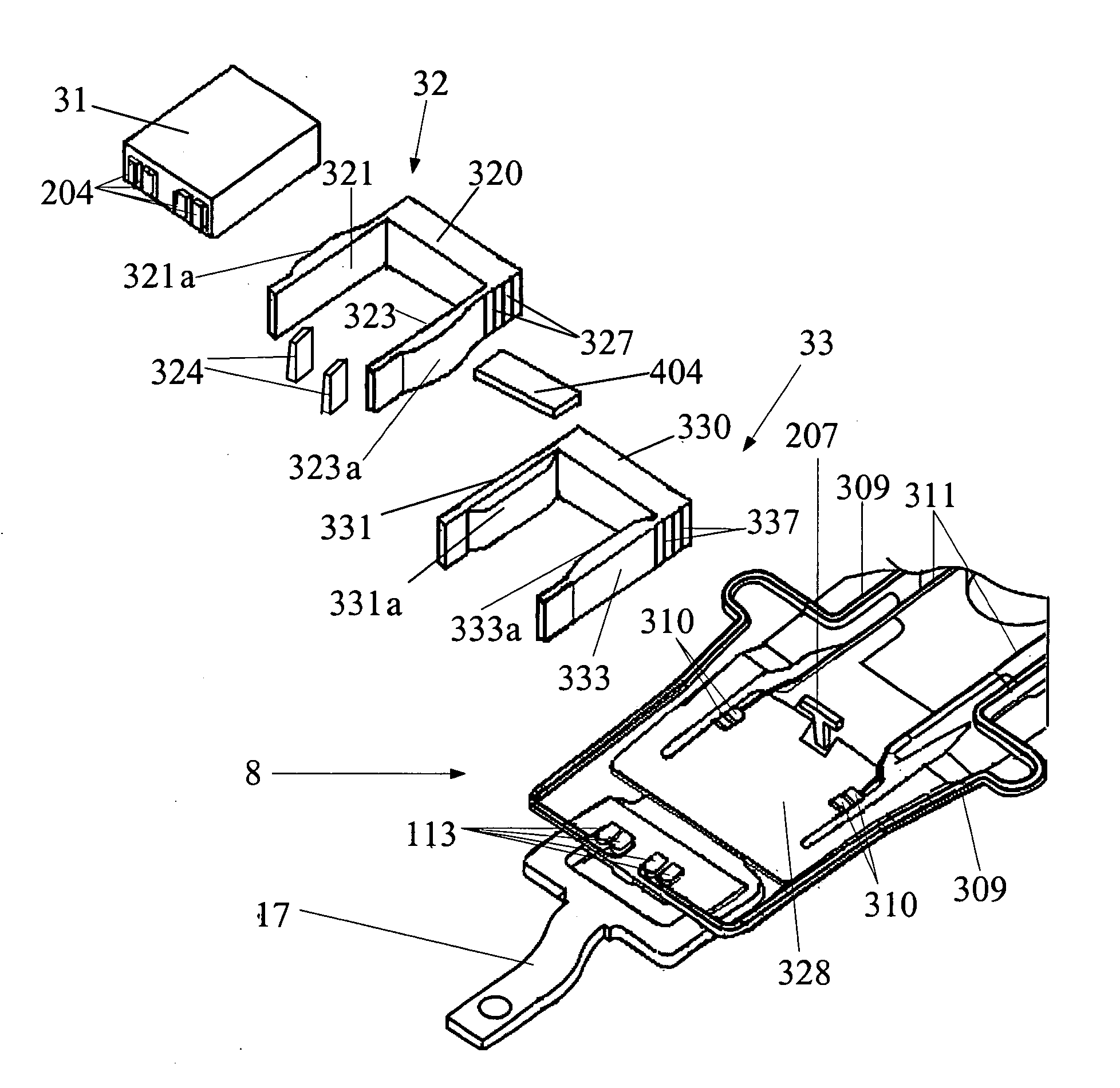
[0041] Referring to the FIG. 5, according to the invention, the frame is also a U-shaped frame which comprises two side plates 331, 333 and a bottom plate 330 to connect with the two side plates 331, 333. When the frame is bonded with micro-actuator 32, the side beams 321, 323 extending from the bottom beam 320 in a first direction while the side plate 331, 333 extending from the bottom plate 330 in an same direction as the first direction. Each of the side plates 331, 333 has a plurality of electrical bonding pads 337 corresponding to the electrical bonding pads 310. The U-shaped frame can be made of metal (i.e. stainless steel), ceramic, silicon or polymer. Two PZT pieces 331a, 333a are respectively bonded on the side plates 331, 333 by traditional bonding method, such as epoxy bonding, anisotropic conductive film (ACF). In an embodiment, the PZT pieces 331a is bonded to an inner side of the side plates 331, and the PZT pieces 333a is bonded to an inner side of the side plates 333...

second embodiment

[0048] According to the invention, referring to FIG. 9a, the micro-actuator 32 and the vibration canceller 33 can be bonded together as the following status: the side beams 321, 323 extending from the bottom beam 320 in a first direction while the side plate 331, 333 extending from the bottom plate 330 in an opposite direction to the first direction.

third embodiment

[0049] According to the invention, referring to FIG. 9b, the frames of the micro-actuator 32 and the vibration canceller 33 can be integrally formed as a frame which has an integral bottom plate 23, and two side plates 27, 29. Two gaps 25 are respectively formed in the two side plates 27, 29, and thus divided the side plate 27 as a first side plate 321′ and a second side plate 331′, and divided the side plate 29 as a first side plate 323′ and a second side plate 333′.


PUM


Abstract

A HGA of the invention includes a slider, a micro-actuator for adjusting the position of the slider; a suspension to load the slider and the micro-actuator; and a vibration canceller interposed between the micro-actuator and the suspension. The micro-actuator includes a first base-part plate, a pair of actuator side arms extending from the first base-part plate in a first direction, and at least one of side arms has a piezoelectric element thereon. The vibration canceller includes a second base-part plate to connect with the micro-actuator and the suspension; and at least one canceling arm extending from the second base-part plate in the first direction or in a second direction, wherein at least one of canceling arms has a piezoelectric element thereon. The invention also discloses a disk drive with the vibration canceller.

Description

FIELD OF THE INVENTION [0001] The present invention relates to disk drive units, and particularly relates to a micro-actuator unit and a head gimbal assembly with vibration canceller. BACKGROUND OF THE INVENTION [0002] Disk drives are information storage devices that use magnetic media to store data. Referring to FIG. 1a, a typical disk drive in related art has a magnetic disk and a drive arm to drive a head gimbal assembly 277 (HGA) (the HGA 277 has a suspension (not labeled) with a slider 203 mounted thereon). The disk is mounted on a spindle motor which causes the disk to spin and a voice-coil motor (VCM) is provided for controlling the motion of the drive arm and thus controlling the slider 203 to move from track to track across the surface of the disk to read data from or write data to the disk. [0003] However, because of the inherent tolerance resulting from VCM and the suspension that exists in the displacement ( off track) of the slider 203, the slider 203 can not attain a q...

Claims


Application Information

Patent Timeline
IPC IPC(8): G11B5/56
CPCG11B5/5552
Inventor YAO, MINGGAOSHIRAISHI, MASASHI
Owner SAE MAGNETICS (HK) LTD
Why Eureka
Try Eureka