
Apparatus and device unit for use in the apparatus

a technology for devices and apparatuses, applied in the direction of electrographic processes, instruments, gearing, etc., can solve the problems of large storage space or facilities, relatively complicated management of storage items, and the effect of restoring to the original sta

Inactive Publication Date: 2006-08-03
RICOH KK
View PDF2 Cites 15 Cited by
  • Summary
  • Abstract
  • Description
  • Claims
  • Application Information

AI Technical Summary

Benefits of technology

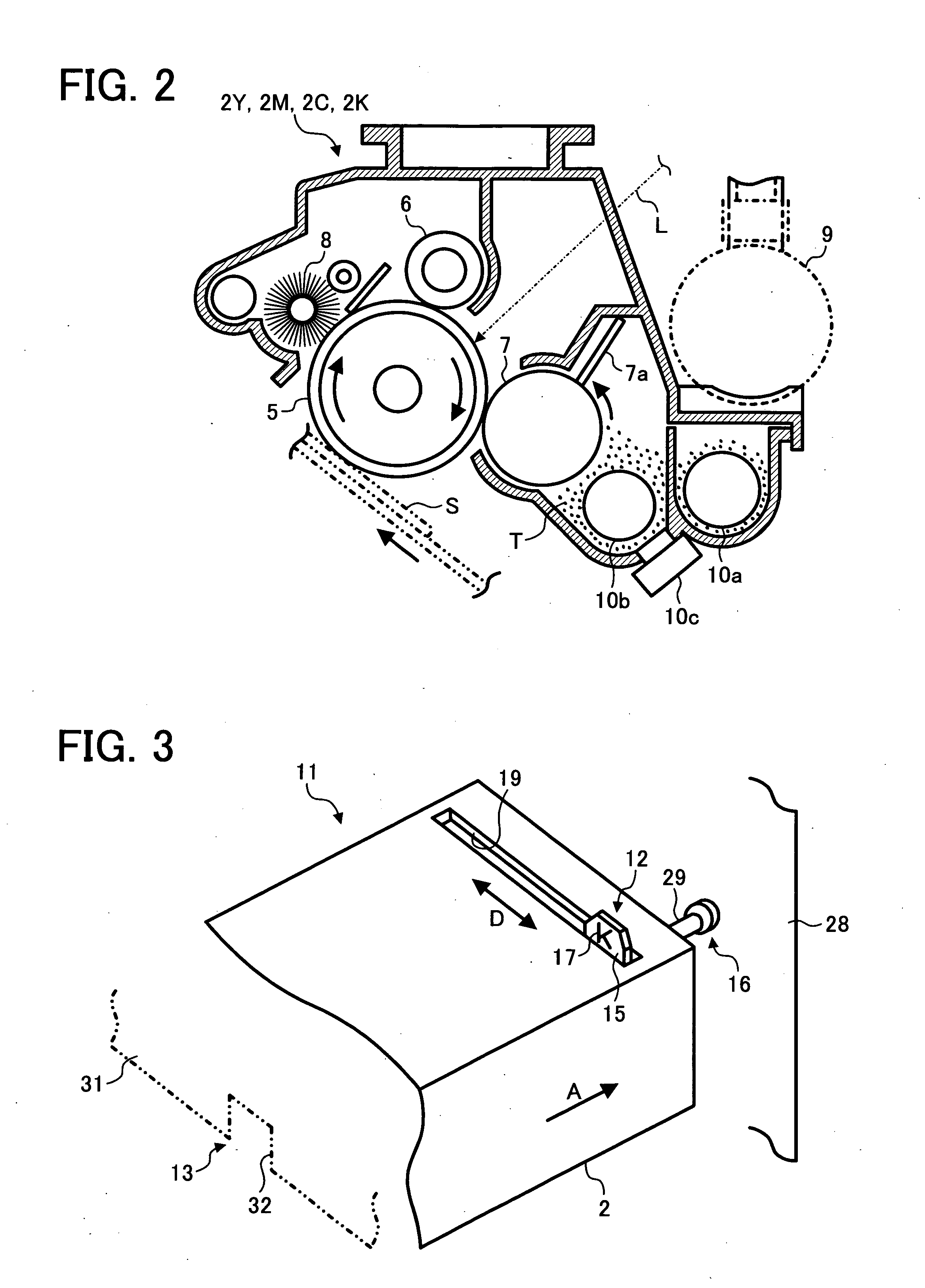
[0022] In the device unit, the apparatus may be an image forming apparatus. In this case, the device unit may be a development device of the image forming apparatus. Further, the development device may be a c

Problems solved by technology

As a result, a larger storage space or facility is necessary, and management of storage items is relatively complicated.
Thus, in the image forming apparatus, even when a user has erroneously installed a process cartridge once installed to and used at an installation part for a certain color to another installation part for another color, the image forming apparatus is not operated or a warning is given to the user, so that the inconvenience, which might have been caused due to such erroneous installation of the process cartridge, can be voided.
In the above-described image forming apparatus, however, because the information as to the color of toner first supplied to each process cartridge is electrically written in the storage device of the process cartridge, unless installation of the process cartridge has been completed, it is not known that the process cartridge has been installed to a wrong installation part, which is inconvenient.
In this case, however, if aprotrusion part of a process cartridge is bent or damaged for some reason other than installing the process cartridge to an installation part and when the process cartridge has been installed to an installation part, if the operation of the image forming apparatus is restricted or a warning is generated, the reason of restriction or warning is unknown to the user, which is troublesome.
Further, the bent or damaged protrusion part of the process cartridge cannot be restored to the original state, so that it is hard to reuse the protrusion part as the mechanical device for storing the information as to the color of toner first supplied to the process cartridge.
Furthermore, even if the plurality of protrusion parts is kept together and is arranged in one location, it is relatively difficult to recognize the information as to the color of toner first supplied to the process cartridge based on the outer appearance of the plurality of protrusion parts at first glance, so that the possibility that the process cartridge is installed to a wrong installation part cannot be avoided.
That is, even when the user could recognize that the process cartridge has been installed to a wrong installation part, it is relatively hard to recognize the correct installation part for the process cartridge from the outer appearance of the process cartridge, which is inconvenient.

Method used


Image

  • Apparatus and device unit for use in the apparatus
  • Apparatus and device unit for use in the apparatus
  • Apparatus and device unit for use in the apparatus

Examples


Embodiment Construction

[0038] Referring now to the drawings, wherein like reference numerals designate identical or corresponding parts throughout the several views, preferred embodiments of the present invention are described.

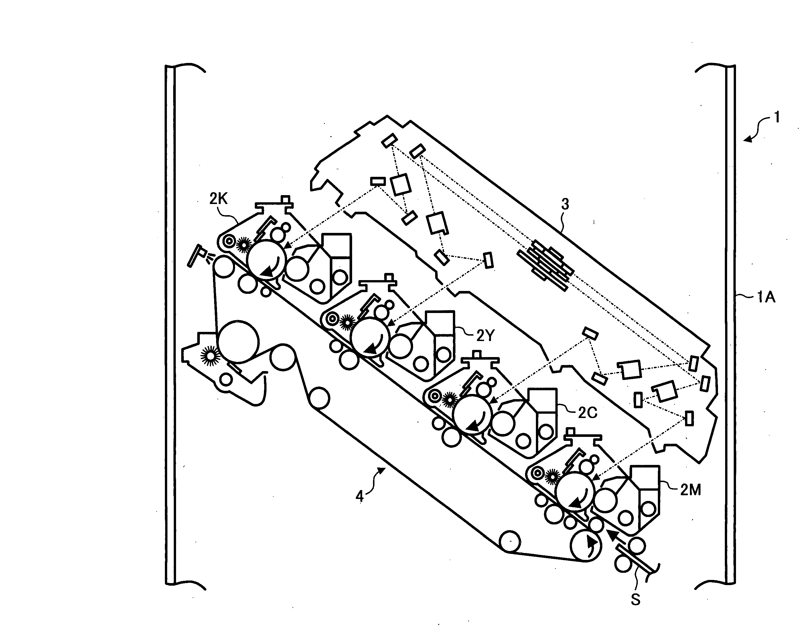
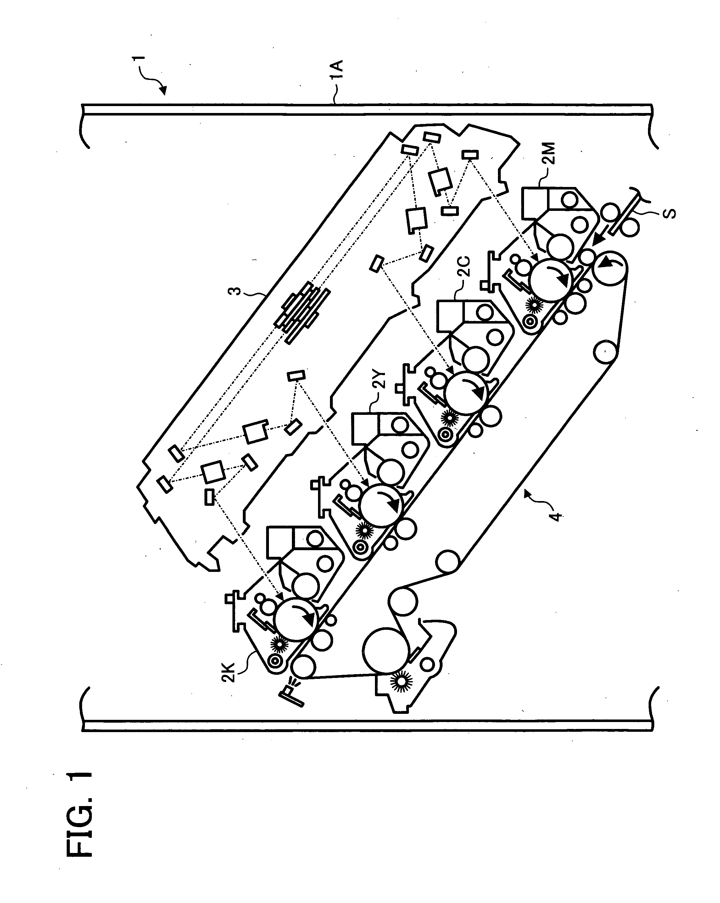
[0039]FIG. 1 is a front view schematically illustrating a configuration of an image forming apparatus as an example of an apparatus having a plurality of installation parts according to the first embodiment of the present invention.

[0040] An image forming apparatus 1 employs a tandem-type image forming method using four photoconductor drums for forming toner images of magenta, cyan, yellow, and black, and includes, as illustrated in FIG. 1, photoconductor units 2K, 2Y, 2C, and 2M, each including a photoconductor drum. Each of photoconductor units 2K, 2Y, 2C, and 2M serves as a device unit according to the first embodiment of the present invention, and is configured to be detachably installable to any one of four installation parts provided in a main body 1A for installing the phot...


PUM


Abstract

An apparatus includes a plurality of installation parts, to each of which a device unit is detachably installed to be used, and a restriction device configured to restrict the device unit having been installed in an unused state to and uninstalled from any one of the plurality of installation parts from being installed to any other installation part of the plurality of installation parts.

Description

CROSS-REFERECE TO RELATED APPLICATIONS [0001] The present application claims priority and contains subject matter related to Japanese Patent Application No. 2004-367515 filed in the Japanese Patent Office on Dec. 20, 2004 and the entire contents of which are hereby incorporated herein by reference. BACKGROUND OF THE INVENTION [0002] 1. Field of the Invention [0003] The present invention relates to an apparatus having a plurality of installation parts and a device unit for installation to each installation part of the apparatus. [0004] 2. Discussion of the Background [0005] Generally, when dealers handle or users use various apparatuses, consumable items and replacement parts thereof are kept in stock. For example, when handling or using image forming apparatuses of various kinds, the dealers or the users generally have spare devices of a development device, etc., in stock. The dealers and the users therefore must keep a storage space or facility for such spare devices. [0006] In par...

Claims


Application Information

Patent Timeline
IPC IPC(8): H01Q3/08
CPCB41J2/1755G03G15/10G03G21/1896Y10T74/22G03G21/1647G03G21/1676G03G2221/163
Inventor YOSHIZAWA, HIROSHI
Owner RICOH KK
Learn More