Heat exchanger plates and methods for manufacturing heat exchanger plates

a technology of heat exchangers and heat exchanger plates, which is applied in the direction of manufacturing tools, forging/pressing/hammering equipment, lighting and heating equipment, etc., can solve the problem of needing to trim excess material along the edges of the plates

Inactive Publication Date: 2006-08-03
DANA CANADA CORP
View PDF27 Cites 3 Cited by
  • Summary
  • Abstract
  • Description
  • Claims
  • Application Information

AI Technical Summary

Problems solved by technology

This results in the need to trim excess material along the edges of the plates, particularly between the end portions in which the bosses are formed.

Method used


Image

  • Heat exchanger plates and methods for manufacturing heat exchanger plates
  • Heat exchanger plates and methods for manufacturing heat exchanger plates
  • Heat exchanger plates and methods for manufacturing heat exchanger plates

Examples


Embodiment Construction

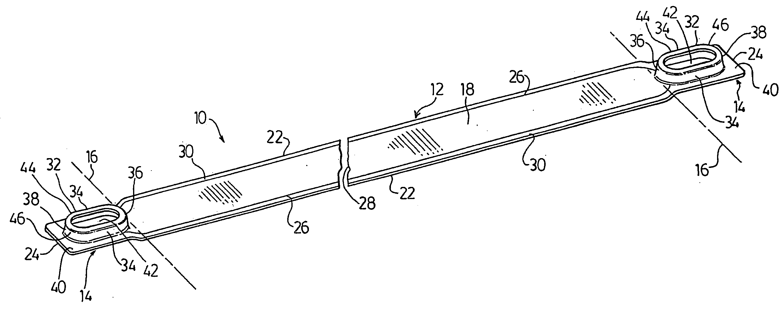
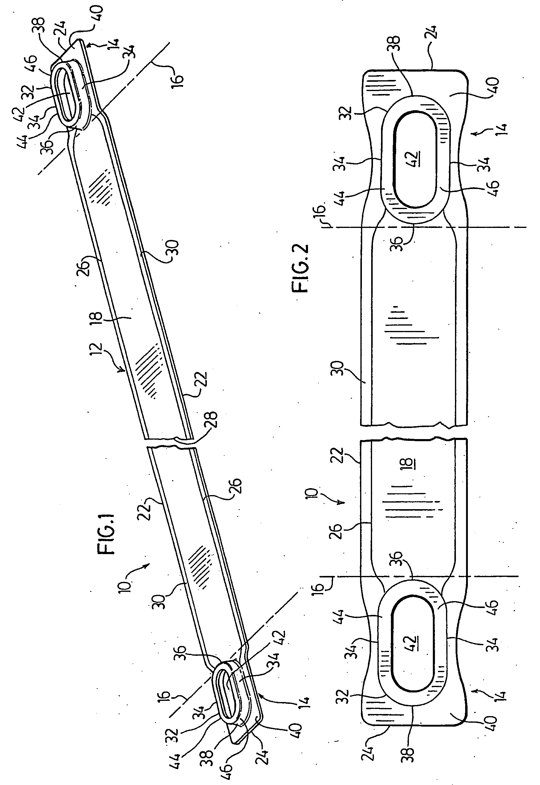
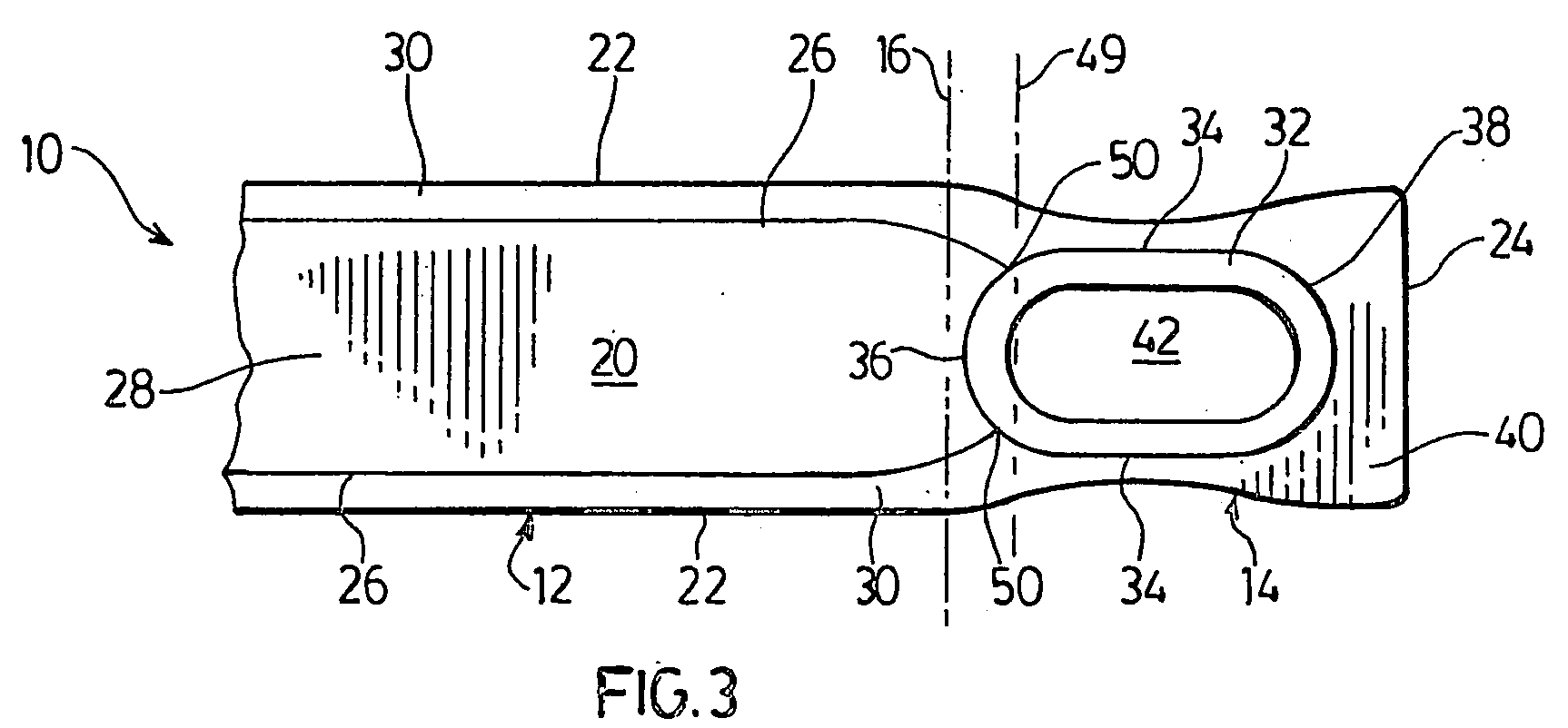
[0029] FIGS. 1 to 3 illustrate a preferred heat exchanger plate 10 according to the present invention. The plate 10 has an elongate central portion 12 located between a pair of end portions 14. Dotted lines 16 shown in FIGS. 1 to 3 indicate the approximate boundaries between the central portion 12 and the end portions 14.

[0030] The plate 10 has an upper surface 18 and an opposed lower surface 20, with elongate side edges 22 extending along the entire length of plate 10 and terminating at end edges 24. Extending along the side edges 22 of plate 10 are a pair of shoulders 26, these shoulders 26 defining a longitudinally extending fluid flow channel 28 extending along the lower surface 20 of plate 10. The fluid flow channel 28 preferably extends along substantially the entire central portion 12 of plate 10, and may preferably extend beyond dotted lines 16 into the end portions 14 of plate 10. The shoulders 26 are spaced from the side edges 22 so as to form flat peripheral side flanges...


PUM

PropertyMeasurementUnit
lengthaaaaaaaaaa
lengthaaaaaaaaaa
widthaaaaaaaaaa

Abstract

A method for forming heat exchanger plates (10) comprises formation of a fluid flow channel (28) along the edges (22) of a sheet metal strip or blank, and formation of a pair of raised end bosses. The raised end bosses (32) are elongated in the longitudinal dimension and are formed within the final width dimension of the plate so as to avoid the need for trimming of excess material along the edges of the plate. The method generates less scrap than prior art processes using progressive stamping, and also permits variation of the plate lengths.

Description

FIELD OF THE INVENTION [0001] The invention relates to methods for manufacturing plates for heat exchangers, particularly to methods in which generation of scrap is reduced, and to heat exchanger plates made by these methods. BACKGROUND OF THE INVENTION [0002] Heat exchangers are commonly made from multiple stacked plate pairs which define coolant flow passages extending between a pair of headers. As shown in FIG. 1 of U.S. Pat. No. 6,273,183 issued on Aug. 14, 2001 to So et al., the plates of each pair are arranged in back-to-back relation and are joined together at their peripheral edges. The plates have raised central portions which define a flow passage therebetween and in which turbulizers may be located. Raised bosses are provided at the ends of the plates, and are apertured to provide inlet and outlet openings. When the heat exchanger is assembled, the bosses are aligned and in communication with one another thereby forming a pair of headers. Expanded metal fins may then be l...

Claims


Application Information

Patent Timeline
Patent Type & Authority Applications(United States)
IPC IPC(8): F28D1/02B21D31/00B21D53/02F28D1/03
CPCB21D53/02F28D1/0333Y10T29/53113Y10T29/49368Y10T29/49833Y10T29/4935Y10T29/49366
Inventor ZURAWEL, PETERDUKE, BRIAN ERNESTCARON, RAYMOND R.LAMBERT, CRAIGLUVISOTTO, ERIC
Owner DANA CANADA CORP
Why Eureka
Try Eureka